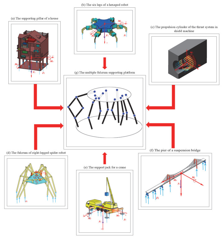
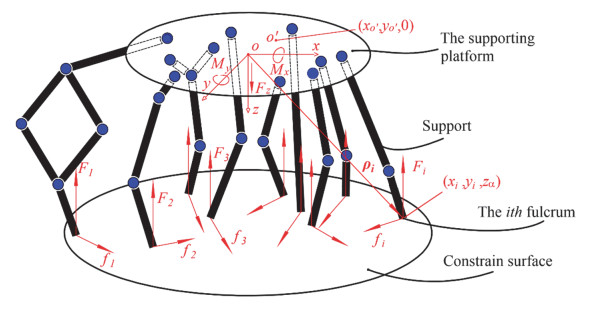
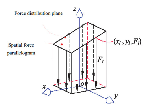
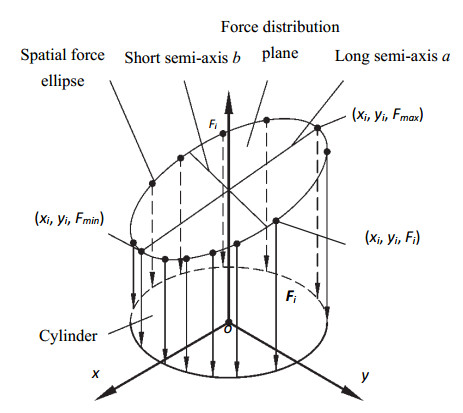
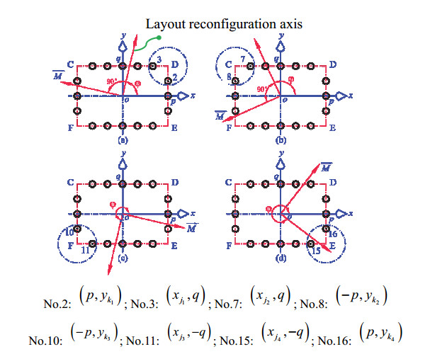
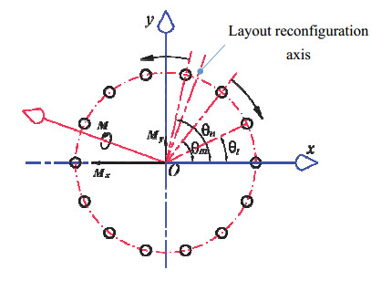
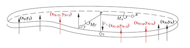
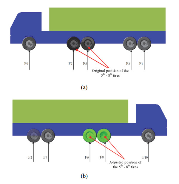
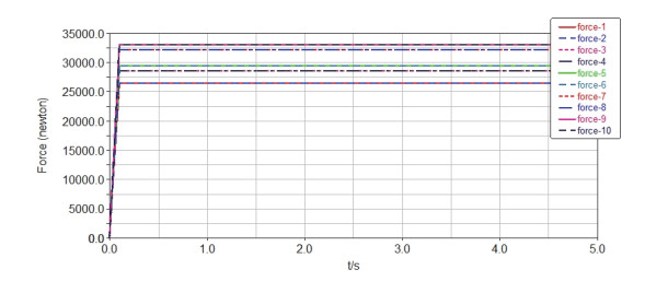
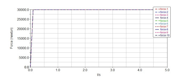
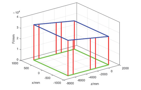
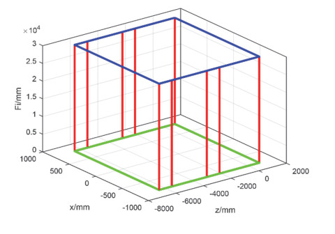
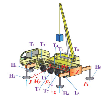
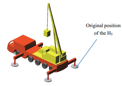
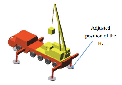
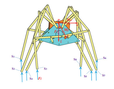
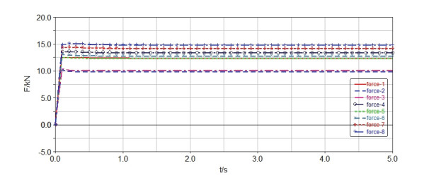
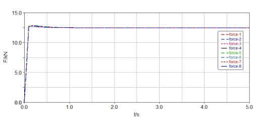
This study aims to investigate the force transmission characteristics of a multiple-fulcrum supporting platform, and the significance of this paper is to creatively put forward the law of uniform force characteristics of multiple-fulcrum supporting platform with heavy loads and layout reconfiguration methods to realize the law. In this paper, firstly, a force transmission model for the multiple-fulcrum supporting platform has been constructed, the relationship between force transmission characteristics and layout parameters for all fulcrums has been discussed in detail, and the layout law for all fulcrums with the same supporting force has been discovered. Then, layout reconfiguration methods have been proposed to realize the uniform force characteristics of all fulcrums under different types of constraint surfaces (rectangular or square constrained surface, circular constrained surface, and unconstrained surface). Finally, layout reconfiguration methods have been applied to some engineering problems by ADAMS simulation. The simulation results show that the supporting force of all fulcrums in the supporting platform is equal when the layout central point (LCP) of all fulcrums is coincident with the force equivalent point (FEP) of external loads. The results provide theoretical guidance and support for the reconfiguration of multiple-fulcrum supporting platforms that can realize uniform forces among all fulcrums.
Citation: Kongshu Deng, Yicheng Ding, Zhurong Yin, Lu Zeng, Hailaing Wu, Dilei Qian. Force transmission characteristics in a multiple-fulcrum supporting platform with heavy loads[J]. Mathematical Biosciences and Engineering, 2020, 17(4): 3329-3355. doi: 10.3934/mbe.2020189
This study aims to investigate the force transmission characteristics of a multiple-fulcrum supporting platform, and the significance of this paper is to creatively put forward the law of uniform force characteristics of multiple-fulcrum supporting platform with heavy loads and layout reconfiguration methods to realize the law. In this paper, firstly, a force transmission model for the multiple-fulcrum supporting platform has been constructed, the relationship between force transmission characteristics and layout parameters for all fulcrums has been discussed in detail, and the layout law for all fulcrums with the same supporting force has been discovered. Then, layout reconfiguration methods have been proposed to realize the uniform force characteristics of all fulcrums under different types of constraint surfaces (rectangular or square constrained surface, circular constrained surface, and unconstrained surface). Finally, layout reconfiguration methods have been applied to some engineering problems by ADAMS simulation. The simulation results show that the supporting force of all fulcrums in the supporting platform is equal when the layout central point (LCP) of all fulcrums is coincident with the force equivalent point (FEP) of external loads. The results provide theoretical guidance and support for the reconfiguration of multiple-fulcrum supporting platforms that can realize uniform forces among all fulcrums.

| [1] |
D. M. Gan, J. S. Dai, L. D. Seneviratne, Variable motion/force transmissibility of a metamorphic parallel mechanism with reconfigurable 3T and 3R motion, J. Mech. Rob., 8 (2016), 051001. doi: 10.1115/1.4032409

|
| [2] |
D. M. Gan, J. S. Dai, Q. Z. Liao, Mobility change in two types of metamorphic parallel mechanisms, J. Mech. Rob., 1 (2009), 041007. doi: 10.1115/1.3211023
|
| [3] |
D. Gan, J. S. Dai, J. Dias, L. Seneviratne, Joint force decomposition and variation in unified inverse dynamics analysis of a metamorphic parallel mechanism, Meccanica, 51 (2016), 1583-1593. doi: 10.1007/s11012-015-0216-y
|
| [4] |
J. S. Dai, Z. Huang, H. Lipkin, Mobility of overconstrained parallel mechanisms, J. Mech. Des., 128 (2006), 220-229. doi: 10.1115/1.1901708
|
| [5] | E. Rodriguez-Leal, J. S Dai, G. R. Pennock, Screw-system-based mobility analysis of a family of fully translational parallel manipulators, Math. Probl. Eng., 2013 (2013). |
| [6] |
Q. A. John, M. L. Joyner, S. Edith, H. Nathaniel, L. Michael, T. C. Jones, An aggregate stochastic model incorporating individual dynamics for predation movements of anelosimus studiosus, Math. Biosci. Eng., 12 (2015), 585-607. doi: 10.3934/mbe.2015.12.585
|
| [7] |
K. S. Deng, X. Q. Tan, L. P Wang, X. Chen, Force transmission characteristics for the non-equidistant arrangement thrust systems of shield tunneling machines, Autom. Constr., 20 (2011), 588-595. doi: 10.1016/j.autcon.2010.11.025
|
| [8] |
K. Z. Zhang, H. D. Yu, Z. P. Liu, X. M. Lai, Dynamic characteristic analysis of TBM tunnelling in mixed-face conditions, Simul. Model Pract. Theory, 18 (2010), 1019-1031. doi: 10.1016/j.simpat.2010.03.005
|
| [9] |
S. Kim, K. Hirota, T. Nozaki, T. Murakami, Human motion analysis and its application to walking stabilization with Cog and ZMP, IEEE Trans. Ind. Inf., 14 (2018), 5178-5186. doi: 10.1109/TII.2018.2830341
|
| [10] | Z. Yu, Q. Zhou, X. Chen, Q. Li, L. Meng, W. Zhang, et al., Disturbance rejection for biped walking using zero-moment point variation based on body acceleration, IEEE Trans. Ind. Inf., 15 (2018), 2265-2276. |
| [11] |
J. Or, A hybrid cpg-zmp controller for the real-time balance of a simulated flexible spine humanoid robot, IEEE Trans. Syst. Man Cybern., 39 (2009), 547-561. doi: 10.1109/TSMCC.2009.2020993
|
| [12] | D. A. Messuri, Optimization of the locomotion of a legged vehicle with respect to maneuverability, The Ohio State University, (1985). |
| [13] |
Z. W. Zhu, M. Gu, Z. Q. Chen, Wind tunnel and CFD study on identification of flutter derivatives of a long-span self-anchored suspension bridge, Comput. Aided Civ. Inf. Eng., 22 (2007), 541-554. doi: 10.1111/j.1467-8667.2007.00509.x
|
| [14] |
R. Q. Wu, W. Zhang, M. H. Yao, Nonlinear dynamics near resonances of a rotor-active magnetic bearings system with 16-pole legs and time varying stiffness, Mech. Syst. Signal. Process., 100 (2018), 113-134. doi: 10.1016/j.ymssp.2017.07.033
|
| [15] |
A. Agudo, F. Moreno-Noguer, Combining local-physical and global-statistical models for sequential deformable shape from motion, Int. J. Comput. Vision, 122 (2017), 371-387. doi: 10.1007/s11263-016-0972-8
|
| [16] | J. T. Adams, Hamiltonian principles, Simon Publications, (2001). |
| [17] | H. W. Zhang, W. X. Zhong, Y. P. Li, Stress singularity analysis at crack tip on bi-material interfaces based on hamiltonian principle, Acta. Mech. Solida Sin., 2 (1996), 124-138. |
| [18] | K. S. Deng, B. L. Meng, C. Xiang, Adaptability to stratum characteristics for layout of thrust system in tunneling machines based on variation coefficient, Adv. Mech. Eng., 8 (2016), 1-9. |
| [19] |
K. S. Deng, C. Xiang, B. L. Meng, H. G. Wang, A force transmission assessment method for thrust system in shield machines based on the relative coefficient in compound ground, Autom. Constr., 83 (2017), 354-359. doi: 10.1016/j.autcon.2017.07.002
|
| [20] | B. Cai, A three-story building bollapsed on xixia road in sheshan town, Min Dong Daily, 2016. Available from: http://115.236.76.50/mdrb_ty/html/2016-04/12/content_3_3.htm. |
| [21] |
N. L. Nguyen, D. E. Meltzer, Visualization tool for 3-D relationships and the right-hand rule, Phys. Teach., 43 (2005), 155-157. doi: 10.1119/1.1869425
|
| [22] | X. Liang, On the crack evolution and failure form of concrete specimens based on minimum energy principle, Multimedia Tools Appl., 2019 (2019), 1-10. |
| [23] | A. A. Tsonis, The principle of minimum energy consumption, in Randomnicity: Rules and Randomness in the Realm of the Infinite, World Scientific, 2008. |
| [24] |
V. Cavina, A. Mari, V. Giovannetti, Slow dynamics and thermodynamics of open quantum systems, Phys. Rev. Lett., 119 (2017), 050601. doi: 10.1103/PhysRevLett.119.050601
|
| [25] | C. S. Li, Y. Zhang, Analysis on teaching of quasi-static process and related physics concepts, Phys. Bull., 3 (2016), 22-24. |
| [26] |
Y. Wang, J. Wang, H. Lischka, Lagrange function method for energy optimization directly in the space of natural orbitals, Int. J. Quantum Chem., 117 (2017), e25376. doi: 10.1002/qua.25376
|
| [27] | Z. Dostál, Linear algebra, in Optimal Quadratic Programming Algorithms, Springer Science & Business Media, 2009. |
| [28] | H. C. Xu, Vibration response of flexible spur ring gear with elastic foundation under internal excitation, J. Mech. Eng., 54 (2018), 161. |
| [29] | X. M. Zhang, L. B. Zhu, A. W. Wang, S. H. Yang, M. Y. Hu, Superficial discussion on new framework of static equilibrium, Appl. Mech. Mater., 670 (2014), 691-695. |
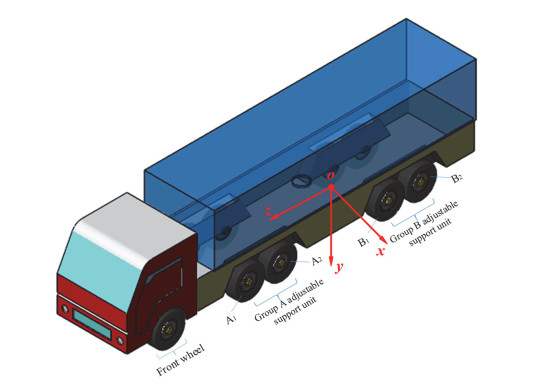
| [30] | Q. F. Cui, A dynamic simulation design of a ladder fire truck based on ADAMS, Appl. Mech. Mater., 670 (2014), 843-846. |
| [31] |
K. Man, A. Damasio, Homeostasis and soft robotics in the design of feeling machines, Nature Mach. Intel., 1 (2019), 446-452. doi: 10.1038/s42256-019-0103-7
|

Figures(24) / Tables(4)

Kongshu Deng, Yicheng Ding, Zhurong Yin, Lu Zeng, Hailaing Wu, Dilei Qian. Force transmission characteristics in a multiple-fulcrum supporting platform with heavy loads[J]. Mathematical Biosciences and Engineering, 2020, 17(4): 3329-3355. doi: 10.3934/mbe.2020189


 DownLoad: