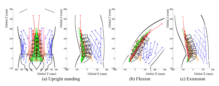
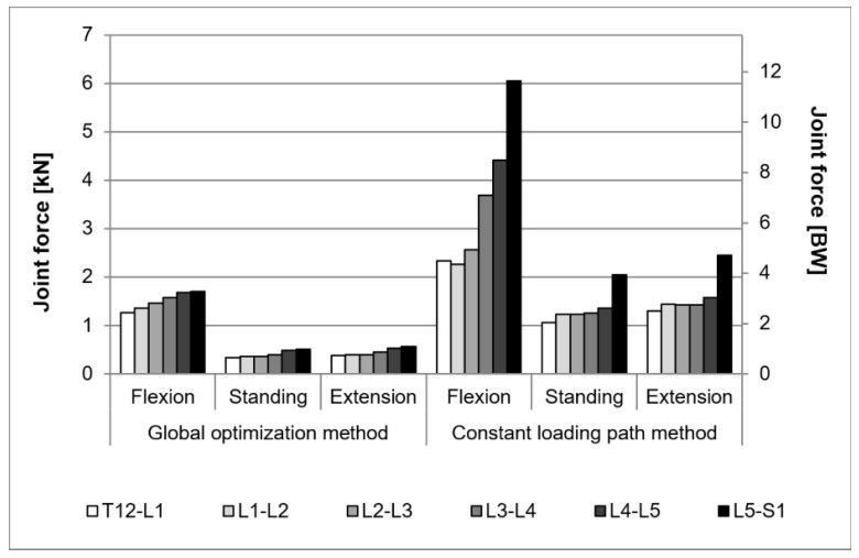
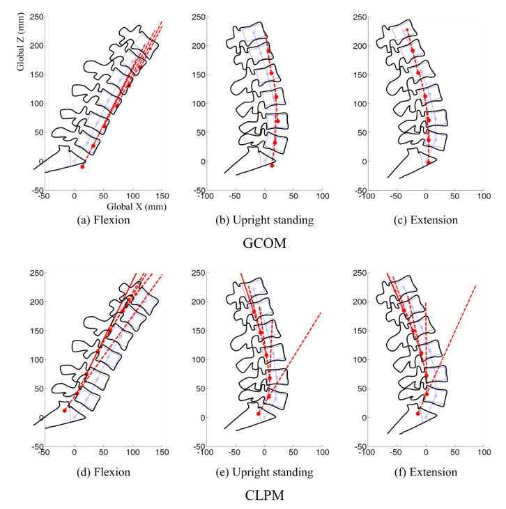
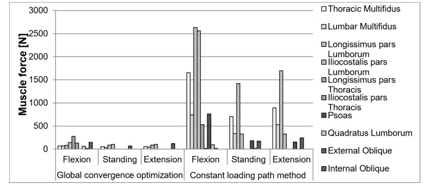
Computational models and inverse dynamic optimization methods are used to predict in-vivo spinal loading. Spinal force is conventionally predicted using the constant loading path method, which is based on the concept that the physiological directions of the spine loads follow the same path of the spinal curve. However, the global convergence optimization method, in which the instantaneous center of rotation of the joint should be also predicted, is necessary for accurate prediction of joint forces of the human body. In this study, we investigate the joint forces, instantaneous centers of rotation, and muscle forces of the human lumbar spine using both global convergence optimization method and constant loading path method during flexion, upright standing, and extension postures. The joint forces predicted using the constant loading path method were 130%, 234%, and 253% greater than those predicted using the global convergence optimization method for the three postures. The instantaneous centers of rotation predicted using the global convergence optimization method were segment level-dependent and moved anteriorly in the flexion and posteriorly in the extension, whereas those predicted using the constant loading path method moved posteriorly in both the flexion and extension. The data indicated that compared to the global convergence optimization method, the constant loading path method introduces additional constraints to the spinal joint model, and thus, it results in greater joint and muscle forces.
Citation: Won Man Park, Young Joon Kim, Shaobai Wang, Yoon Hyuk Kim, Guoan Li. Investigation of lumbar spine biomechanics using global convergence optimization and constant loading path methods[J]. Mathematical Biosciences and Engineering, 2020, 17(4): 2970-2983. doi: 10.3934/mbe.2020168
Computational models and inverse dynamic optimization methods are used to predict in-vivo spinal loading. Spinal force is conventionally predicted using the constant loading path method, which is based on the concept that the physiological directions of the spine loads follow the same path of the spinal curve. However, the global convergence optimization method, in which the instantaneous center of rotation of the joint should be also predicted, is necessary for accurate prediction of joint forces of the human body. In this study, we investigate the joint forces, instantaneous centers of rotation, and muscle forces of the human lumbar spine using both global convergence optimization method and constant loading path method during flexion, upright standing, and extension postures. The joint forces predicted using the constant loading path method were 130%, 234%, and 253% greater than those predicted using the global convergence optimization method for the three postures. The instantaneous centers of rotation predicted using the global convergence optimization method were segment level-dependent and moved anteriorly in the flexion and posteriorly in the extension, whereas those predicted using the constant loading path method moved posteriorly in both the flexion and extension. The data indicated that compared to the global convergence optimization method, the constant loading path method introduces additional constraints to the spinal joint model, and thus, it results in greater joint and muscle forces.

| [1] |
N. Arjmand, A. Shirazi-Adl, Model and in vivo studies on human trunk load partitioning and stability in isometric forward flexions, J. Biomech., 39 (2006), 510-521. doi: 10.1016/j.jbiomech.2004.11.030

|
| [2] |
H. J. Wilke, P. Neef, M. Caimi, T. Hoogland, L. E. Claes, New in vivo measurements of pressures in the intervertebral disc in daily life, Spine (Phila. Pa. 1976), 24 (1999), 755-762. doi: 10.1097/00007632-199904150-00005
|
| [3] |
H. J. Wilke, P. Neef, B. Hinz, H. Seidel, L. Claes, Intradiscal pressure together with anthropometric data-a data set for the validation of models, Clin. Biomech., 16 (2001), S111-S126. doi: 10.1016/S0268-0033(00)00103-0
|
| [4] |
A. Rohlmann, S. Neller, L. Claes, G. Bergmann, H. J. Wilke, Influence of a follower load on intradiscal pressure and intersegmental rotation of the lumbar spine, Spine (Phila. Pa. 1976), 26 (2001), E557-E561. doi: 10.1097/00007632-200112150-00014
|
| [5] |
N. Arjmand, D. Gagnon, A. Plamondon, A. Shirazi-Adl, C. Larivière, Comparison of trunk muscle forces and spinal loads estimated by two biomechanical models, Clin. Biomech., 24 (2009), 533-541. doi: 10.1016/j.clinbiomech.2009.05.008
|
| [6] |
I. A. F. Stokes, M. Gardner-Morse, Lumbar spine maximum efforts and muscle recruitment patterns predicted by a model with multijoint muscles and joints with stiffness, J. Biomech., 28 (1995), 173-186. doi: 10.1016/0021-9290(94)E0040-A
|
| [7] |
I. A. F. Stokes, M. Gardner-Morse, Lumbar spinal muscle activation synergies predicted by multi-criteria cost function, J. Biomech., 34 (2001), 733-740. doi: 10.1016/S0021-9290(01)00034-3
|
| [8] |
I. A. F. Stokes, M. G. Gardner-Morse, S. M. Henry, Intra-abdominal pressure and abdominal wall muscular function: Spinal unloading mechanism, Clin. Biomech., 25 (2010), 859-866. doi: 10.1016/j.clinbiomech.2010.06.018
|
| [9] |
K. S. Han, A. Rohlmann, S. J. Yang, B. S. Kim, T. H. Lim, Spinal muscles can create compressive follower loads in the lumbar spine in a neutral standing posture, Med. Eng. Phys., 33 (2011), 472-478. doi: 10.1016/j.medengphy.2010.11.014
|
| [10] |
S. Zeinali-Davarani, H. Hemami, K. Barin, A. Shirazi-Adl, M. Parnianpour, Dynamic stability of spine using stability-based optimization and muscle spindle reflex, IEEE Trans. Neural Syst. Rehabil. Eng., 16 (2008), 106-118. doi: 10.1109/TNSRE.2007.906963
|
| [11] | K. Kim, Y. H. Kim, S. Lee, Shear force allowance in lumbar spine under follower load in neutral standing posture, Acta Bioeng. Biomech., 12 (2010), 49-53. |
| [12] |
K. Kim, Y. H. Kim, S. K. Lee, Investigation of optimal follower load path generated by trunk muscle coordination, J. Biomech., 44 (2011), 1614-1617. doi: 10.1016/j.jbiomech.2011.03.010
|
| [13] |
M. Dreischarf, T. Zander, G. Bergmann, A. Rohlmann, A non-optimized follower load path may cause considerable intervertebral rotations, J. Biomech., 43 (2010), 2625-2628. doi: 10.1016/j.jbiomech.2010.05.033
|
| [14] |
G. Li, J. E. Pierce, J. H. Herndon, A global optimization method for prediction of muscle forces of human musculoskeletal system, J. Biomech., 39 (2006), 522-529. doi: 10.1016/j.jbiomech.2004.11.027
|
| [15] |
J. E. Pierce, G. Li, Muscle forces predicted using optimization methods are coordinate system dependent, J. Biomech., 38 (2005), 695-702. doi: 10.1016/j.jbiomech.2004.05.016
|
| [16] |
K. N. An, B. M. Kwak, E. Y. Chao, B. F. Morrey, Determination of muscle and joint forces: a new technique to solve the indeterminate problem, J. Biomech. Eng., 106 (1984), 364-367. doi: 10.1115/1.3138507
|
| [17] |
N. Bogduk, J. E. Macintosh, M. J. Pearcy, A universal model of the lumbar back muscles in the upright position, Spine (Phila. Pa. 1976), 17 (1992), 897-913. doi: 10.1097/00007632-199208000-00007
|
| [18] |
I. A. F. Stokes, M. Gardner-Morse, Quantitative anatomy of the lumbar musculature, J. Biomech., 32 (1999), 311-316. doi: 10.1016/S0021-9290(98)00164-X
|
| [19] |
M. Damavandi, N. Farahpour, P. Allard, Determination of body segment masses and centers of mass using a force plate method in individuals of different morphology, Med. Eng. Phys., 31 (2009), 1187-1194. doi: 10.1016/j.medengphy.2009.07.015
|
| [20] |
D. J. Pearsall, J. G. Reid, R. Ross, Inertial properties of the human trunk of males determined from magnetic resonance imaging, Ann. Biomed. Eng., 22 (1994), 692-706. doi: 10.1007/BF02368294
|
| [21] |
A. Shirazi-Adl, M. El-Rich, D. G. Pop, M. Parnianpour, Spinal muscle forces, internal loads and stability in standing under various postures and loads-Application of kinematics-based algorithm, Eur. Spine J., 14 (2005), 381-392. doi: 10.1007/s00586-004-0779-0
|
| [22] | D. A. Winter, Biomechanics and Motor Control of Human Movement: Fourth Edition, Wiley (2009), 82-106. |
| [23] |
M. Dreischarf, A. Rohlmann, R. Zhu, H. Schmidt, T. Zander, Is it possible to estimate the compressive force in the lumbar spine from intradiscal pressure measurements? A finite element evaluation, Med. Eng. Phys., 35 (2013), 1385-90. doi: 10.1016/j.medengphy.2013.03.007
|
| [24] |
M. J. Pearcy, N. Bogduk, Instantaneous axes of rotation of the lumbar intervertebral joints, Spine (Phila. Pa. 1976), 13 (1988), 1033-1041. doi: 10.1097/00007632-198809000-00011
|
| [25] |
S. H. Zhou, I. D. McCarthy, A. H. McGregor, R. R. H. Coombs, S. P. F. Hughes, Geometrical dimensions, of the lumbar vertebrae-Analysis of data from digitised CT images, Eur. Spine J., 9 (2000), 242-248. doi: 10.1007/s005860000140
|
| [26] |
H. Schmidt, F. Heuer, L. Claes, H. J. Wilke, The relation between the instantaneous center of rotation and facet joint forces-A finite element analysis, Clin. Biomech., 23 (2008), 270-278. doi: 10.1016/j.clinbiomech.2007.10.001
|
| [27] | A. A.White, M. M. Panjabi, Clinical Biomechanics of the Spine, Second edition. Lippincott Williams & Wilkins (1990). |
| [28] |
F. Ghezelbash, N. Arjmand, A. Shirazi-Adl, Effect of intervertebral translational flexibilities on estimations of trunk muscle forces, kinematics, loads, and stability, Comput. Methods Biomech. Biomed. Engin., 18 (2015), 1760-1767. doi: 10.1080/10255842.2014.961440
|
| [29] |
F. Ghezelbash, A. H. Eskandari, A. Shirazi-Adl, N. Arjmand, Z. El-Quaaid, A. Plamondon, Effects of motion segment simulation and joint positioning on spinal loads in trunk musculoskeletal models, J. Biomech., 70 (2018), 149-156. doi: 10.1016/j.jbiomech.2017.07.014
|
| [30] |
G. Li, K. Kawamura, P. Barrance, E. Y. S. Chao, K. Kaufman, Prediction of muscle recruitment and its effect on joint reaction forces during knee exercises, Ann. Biomed. Eng., 26 (1998), 725-733. doi: 10.1114/1.104
|
Figures(6) / Tables(1)

Won Man Park, Young Joon Kim, Shaobai Wang, Yoon Hyuk Kim, Guoan Li. Investigation of lumbar spine biomechanics using global convergence optimization and constant loading path methods[J]. Mathematical Biosciences and Engineering, 2020, 17(4): 2970-2983. doi: 10.3934/mbe.2020168


 DownLoad: