Round-window stimulating transducer is a new solution to treat mixed hearing loss. To uncover the factors affecting the round-window stimulation's performance, we investigated the influence of four main design parameters of round-window stimulating type electromagnetic transducer. Firstly, we constructed a human ear nonlinear lumped parameter model and confirmed its validity by comparing the stapes responses predicted by the model with the experimental data. Following this, an electromagnetic transducer's mechanical model, which simulates the floating mass transducer, was built and coupled to the human ear model; thereby, we established a nonlinear lumped parameter model of implanted human ear under round-window stimulation and verified its reliability. Finally, based on this model, the influences of the four main design parameters, i.e., the excitation voltage, the electromechanical coupling coefficient, the support stiffness, and the preload force, were analyzed. The results show that the change of excitation voltage does not alter the system's natural frequency. Chaotic motion occurs when the electromechanical coupling coefficient is small. Meanwhile, the stapes displacement appears to increase firstly and then decrease with the increase of the electromechanical coupling coefficient. The increase of the support stiffness enlarges the resonance frequency of the stapes displacement and reduces the stapes displacement near the resonance frequency, deteriorating the transducer's hearing compensation at low frequency. The preload force can improve the transducer's hearing compensation performance in mid-high frequency region.
Citation: Zhaohai Liu, Houguang Liu, Jie Wang, Jianhua Yang, Jingbin Hao, Shanguo Yang. Analysis of design parameters of round-window stimulating type electromagnetic transducer by a nonlinear lumped parameter model of implanted human ear[J]. Mathematical Biosciences and Engineering, 2022, 19(3): 2453-2470. doi: 10.3934/mbe.2022113
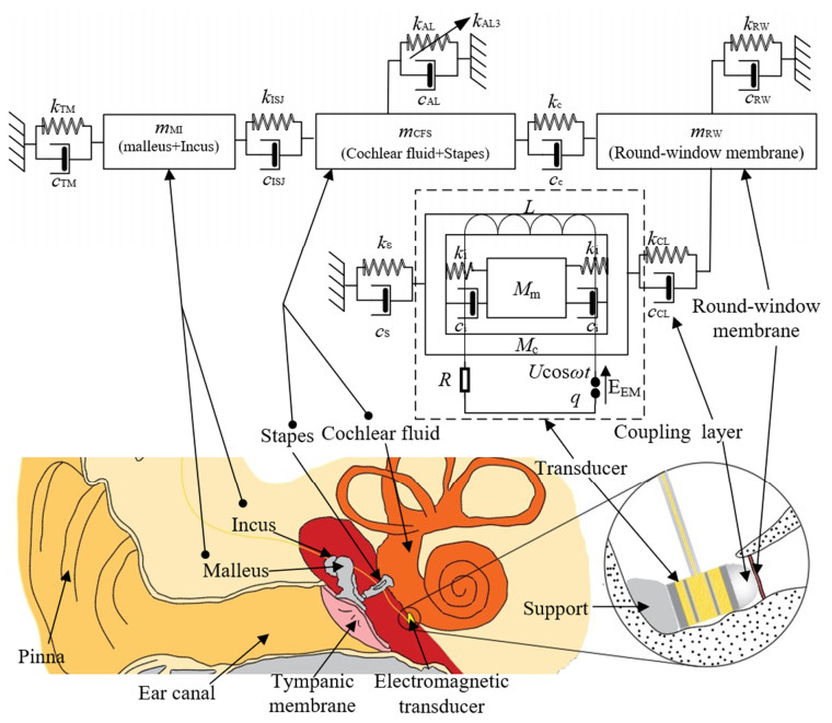
Round-window stimulating transducer is a new solution to treat mixed hearing loss. To uncover the factors affecting the round-window stimulation's performance, we investigated the influence of four main design parameters of round-window stimulating type electromagnetic transducer. Firstly, we constructed a human ear nonlinear lumped parameter model and confirmed its validity by comparing the stapes responses predicted by the model with the experimental data. Following this, an electromagnetic transducer's mechanical model, which simulates the floating mass transducer, was built and coupled to the human ear model; thereby, we established a nonlinear lumped parameter model of implanted human ear under round-window stimulation and verified its reliability. Finally, based on this model, the influences of the four main design parameters, i.e., the excitation voltage, the electromechanical coupling coefficient, the support stiffness, and the preload force, were analyzed. The results show that the change of excitation voltage does not alter the system's natural frequency. Chaotic motion occurs when the electromechanical coupling coefficient is small. Meanwhile, the stapes displacement appears to increase firstly and then decrease with the increase of the electromechanical coupling coefficient. The increase of the support stiffness enlarges the resonance frequency of the stapes displacement and reduces the stapes displacement near the resonance frequency, deteriorating the transducer's hearing compensation at low frequency. The preload force can improve the transducer's hearing compensation performance in mid-high frequency region.

| [1] |
T. Vos, A. A. Abajobir, C. Abbafati, K. M. Abbas, K. H. Abate, F. Abd-Allah, et al., Global, regional, and national incidence, prevalence, and years lived with disability for 328 diseases and injuries for 195 countries, 1990–2016: a systematic analysis for the global burden of disease study 2016, Lancet, 390 (2017), 1211–1259. https://doi.org/10.1016/S0140-6736(17)32154-2. doi: 10.1016/S0140-6736(17)32154-2

|
| [2] |
A. Davis, Population study of the ability to benefit from amplification and the provision of a hearing aid in 55–74-year-old first-time hearing aid users, Int. J. Audiol., 42 (2009), 39–52. https://doi.org/10.3109/14992020309074643. doi: 10.3109/14992020309074643
|
| [3] |
H. Liu, J. Cheng, J. Yang, Z. Rao, G. Cheng, S. Yang, et al., Concept and evaluation of a new piezoelectric transducer for an implantable middle ear hearing device, Sensors, 17 (2017), 2515. https://doi.org/10.3390/s17112515. doi: 10.3390/s17112515
|
| [4] |
I. Y. Park, Y. Shimizu, K. N. O'Connor, S. Puria, J. H. Cho, Comparisons of electromagnetic and piezoelectric floating-mass transducers in human cadaveric temporal bones, Hear Res., 272 (2011), 187–192. https://doi.org/10.1016/j.heares.2010.10.017. doi: 10.1016/j.heares.2010.10.017
|
| [5] |
M. Seidman, T. A. Janz, J. A. Shohet, Totally implantable active middle ear implants, Otolaryngol Clin. North. Am., 52 (2019), 297–309. doi: https://doi.org/10.1016/j.otc.2018.11.011. doi: 10.1016/j.otc.2018.11.011
|
| [6] |
L. Colletti, M. Mandala, V. Colletti, Long-term outcome of round window vibrant soundbridge implantation in extensive ossicular chain defects, Otolaryngol Head Neck Surg., 149 (2013), 134–141. https://doi.org/10.1177/0194599813486255. doi: 10.1177/0194599813486255
|
| [7] |
V. Colletti, S. D. Soli, M. Carner, L. Colletti, Treatment of mixed hearing losses via implantation of a vibratory transducer on the round window, Int. J. Audiol., 45 (2006), 600–608. https://doi.org/10.1080/14992020600840903. doi: 10.1080/14992020600840903
|
| [8] |
G. M. Sprinzl, A. W. Magele, J. Schnabl, V. Koci, The active middle ear implant for the rehabilitation of sensorineural, mixed and conductive hearing losses, Laryngo Rhino Otol., 90 (2011), 560–569. https://doi.org/10.1055/s-0031-1286321. doi: 10.1055/s-0031-1286321
|
| [9] |
A. Arnold, C. Stieger, C. Candreia, F. Pfiffner, M. Kompis, Factors improving the vibration transfer of the floating mass transducer at the round window, Otol. Neurotol., 31 (2010), 122–128. https://doi.org/10.1097/MAO.0b013e3181c34ee0. doi: 10.1097/MAO.0b013e3181c34ee0
|
| [10] |
S. P. Schraven, B. Hirt, E. Goll, A. Heyd, A. W. Gummer, H. P. Zenner, et al., Conditions for highly efficient and reproducible round–window stimulation in humans, Audiol. Neurootol., 17 (2012), 133–138. https://doi.org/10.1159/000333807. doi: 10.1159/000333807
|
| [11] |
H. Maier, R. Salcher, B. Schwab, T. Lenarz, The effect of static force on round window stimulation with the direct acoustic cochlea stimulator, Hear Res., 301 (2013), 115–124. https://doi.org/10.1016/j.heares.2012.12.010. doi: 10.1016/j.heares.2012.12.010
|
| [12] |
X. M. Zhang, R. Z. Gan, A comprehensive model of human ear for analysis of implantable hearing devices, IEEE Trans. Biomed. Eng., 58 (2011), 3024–3027. https://doi.org/10.1109/TBME.2011.2159714. doi: 10.1109/TBME.2011.2159714
|
| [13] |
X. Bie, Y. Y. Tang, M. Zhao, Y. X. Liu, S. Yu, D. Sun, et al., Pilot study of pressure–flow properties in a numerical model of the middle ear, Math. Biosci. Eng., 17 (2020), 2418–2431. https://doi.org/10.3934/mbe.2020131. doi: 10.3934/mbe.2020131
|
| [14] |
K. Fessel, M. H. Holmes, A model for the nonlinear mechanism responsible for cochlear amplification, Math. Biosci. Eng., 11 (2014), 1357–1373. https://doi.org/10.3934/mbe.2014.11.1357. doi: 10.3934/mbe.2014.11.1357
|
| [15] |
H. G. Liu, D. Xu, J. H. Yang, S. G. Yang, G. Cheng, X. S. Huang, Analysis of the influence of the transducer and its coupling layer on round window stimulation, Acta Bioeng. Biomech., 19 (2017), 103–111. https://doi.org/10.5277/ABB-00783-2016-03. doi: 10.5277/ABB-00783-2016-03
|
| [16] |
H. Liu, W. Wang, Y. Zhao, J. Yang, S. Yang, X. Huang, et al., Effect of stimulation sites on the performance of electromagnetic middle ear implant: a finite element analysis, Comput. Biol. Med., 124 (2020), 103918. https://doi.org/10.1016/j.compbiomed.2020.103918. doi: 10.1016/j.compbiomed.2020.103918
|
| [17] |
J. Zhang, D. L. Zou, J. B. Tian, N. Ta, Z. S. Rao, A comparative finite-element analysis of acoustic transmission in human cochlea during forward and reverse stimulations, Appl. Acoust., 145 (2019), 278–289. https://doi.org/10.1016/j.apacoust.2018.10.023. doi: 10.1016/j.apacoust.2018.10.023
|
| [18] |
J. B. Tian, X. S. Huang, Z. S. Rao, N. Ta, L. F. Xu, Finite element analysis of the effect of actuator coupling conditions on round window stimulation, J. Mech. Med. Biol., 15 (2015), 1550048. https://doi.org/10.1142/S0219519415500487. doi: 10.1142/S0219519415500487
|
| [19] |
Y. Chen, W. Yao, Mechanical model of round window membrane under reverse excitation, Appl. Math. Mech., 37 (2016), 1341–1348. https://doi.org/10.1007/s10483-016-2136-9. doi: 10.1007/s10483-016-2136-9
|
| [20] |
B. Feng, R. Z. Gan, Lumped parametric model of the human ear for sound transmission, Biomech. Model Mechan., 3 (2004), 33–47. https://doi.org/10.1007/s10237-004-0044-9. doi: 10.1007/s10237-004-0044-9
|
| [21] |
P. Bowers, J. J. Rosowski, A lumped-element model of the chinchilla middle ear, J. Acoust. Soc. Am., 145 (2019), 1975–1992. https://doi.org/10.1121/1.5094897. doi: 10.1121/1.5094897
|
| [22] |
L. Xue, H. Liu, W. Wang, J. Yang, Y. Zhao, X. Huang, The role of third windows on human sound transmission of forward and reverse stimulations: a lumped-parameter approach, J. Acoust. Soc. Am., 147 (2020), 1478–1490. https://doi.org/10.1121/10.0000846. doi: 10.1121/10.0000846
|
| [23] |
R. Rusinek, A. Weremczuk, Recent advances in periodic vibrations of the middle ear with a floating mass transducer, Meccanica, 55 (2020), 2609–2621. https://doi.org/10.1007/s11012-020-01226-x. doi: 10.1007/s11012-020-01226-x
|
| [24] |
R. Rusinek, Sound transmission in the first nonlinear model of middle ear with an active implant, Math. Probl. Eng., 2020 (2020), 1–23. https://doi.org/10.1155/2020/4580467. doi: 10.1155/2020/4580467
|
| [25] |
K. W. Seong, E. S. Jung, H. G. Lim, J. W. Lee, M. W. Kim, S. H. Woo, et al., Vibration analysis of human middle ear with differential floating mass transducer using electrical model, IEICE T. Inf. Syst., E92–D (2009), 2156–2158. https://doi.org/10.1587/transinf.E92.D.2156. doi: 10.1587/transinf.E92.D.2156
|
| [26] |
R. Rusinek, K. Kecik, Effect of linear electromechanical coupling in nonlinear implanted human middle ear, Mech. Syst. Signal. Pr., 151 (2021), 107391. https://doi.org/10.1016/j.ymssp.2020.107391. doi: 10.1016/j.ymssp.2020.107391
|
| [27] |
C. Heckeler, A. Eiber, Mechanical aspects of the round window stimulation, Procedia IUTAM, 24 (2017), 15–29. https://doi.org/10.1016/j.piutam.2017.08.039. doi: 10.1016/j.piutam.2017.08.039
|
| [28] |
M. Lauxmann, A. Eiber, F. Haag, S. Ihrle, Nonlinear stiffness characteristics of the annular ligament, J. Acoust. Soc. Am., 136 (2014), 1756–1767. https://doi.org/10.1121/1.4895696. doi: 10.1121/1.4895696
|
| [29] |
I. Dobrev, S. Ihrle, C. Roosli, R. Gerig, A. Eiber, A. M. Huber, et al., A method to measure sound transmission via the malleus–incus complex, Hear Res., 340 (2016), 89–98. https://doi.org/10.1016/j.heares.2015.10.016. doi: 10.1016/j.heares.2015.10.016
|
| [30] |
L. Colletti, M. Carner, M. Mandala, S. Veronese, V. Colletti, The floating mass transducer for external auditory canal and middle ear malformations, Otol. Neurotol., 32 (2011), 108–115. https://doi.org/10.1097/MAO.0b013e3181ff752a. doi: 10.1097/MAO.0b013e3181ff752a
|
| [31] |
M. Mandala, L. Colletti, V. Colletti, Treatment of the atretic ear with round window vibrant soundbridge implantation in infants and children: electrocochleography and audiologic outcomes, Otol. Neurotol., 32 (2011), 1250–1255. https://doi.org/10.1097/MAO.0b013e31822e9513. doi: 10.1097/MAO.0b013e31822e9513
|
| [32] |
V. L. Trindade, P. A. Martins, S. Santos, M. P. Parente, R. M. Natal Jorge, A. Santos, et al., Experimental study of the influence of senescence in the biomechanical properties of the temporal tendon and deep temporal fascia based on uniaxial tension tests, J. Biomech., 45 (2012), 199–201. https://doi.org/10.1016/j.jbiomech.2011.09.018. doi: 10.1016/j.jbiomech.2011.09.018
|
| [33] |
J. Tian, X. Huang, Z. Rao, N. A. Ta, L. Xu, Finite element analysis of the effect of actuator coupling conditions on round window stimulation, J. Mech. Med. Biol., 15 (2015), 1550048. https://doi.org/10.1142/S0219519415500487. doi: 10.1142/S0219519415500487
|
| [34] |
D. H. Shin, J. H. Cho, Piezoelectric actuator with frequency characteristics for a middle-ear implant, Sensors, 18 (2018), 1694. https://doi.org/10.3390/s18061694. doi: 10.3390/s18061694
|
| [35] |
H. H. Nakajima, W. Dong, E. S. Olson, J. J. Rosowski, M. E. Ravicz, S. N. Merchant, Evaluation of round window stimulation using the floating mass transducer by intracochlear sound pressure measurements in human temporal bones, Otol. Neurotol., 31 (2010), 506–511. https://doi.org/10.1097/MAO.0b013e3181c0ea9f. doi: 10.1097/MAO.0b013e3181c0ea9f
|
| [36] |
A. Wolf, J. B. Swift, H. L. Swinney, J. A. Vastano, Determining lyapunov exponents from a time series, Physica D, 16 (1985), 285–317. https://doi.org/10.1016/0167-2789(85)90011-9. doi: 10.1016/0167-2789(85)90011-9
|
| [37] |
R. Z. Gan, C. Tao, M. W. Wood, Acoustic-structural coupled finite element analysis for sound transmission in human ear-middle ear transfer function, Med. Eng. Phys., 28 (2006), 395–404. https://doi.org/10.1016/j.medengphy.2005.07.018. doi: 10.1016/j.medengphy.2005.07.018
|
| [38] |
H. G. Liu, Y. Zhao, J. H. Yang, Z. S. Rao, The influence of piezoelectric transducer stimulating sites on the performance of implantable middle ear hearing devices: a numerical analysis, Micromachines, 10 (2019), 782. https://doi.org/10.3390/mi10110782. doi: 10.3390/mi10110782
|
| [39] |
E. P. Hong, M. K. Kim, I. Y. Park, S. H. Lee, Y. Row, J. H. Cho, Vibration modeling and design of piezoelectric floating mass transducer for implantable middle ear hearing devices, IEICE T. Fund. Electr., E90a (2007), 1620–1627. https://doi.org/10.1093/ietfec/e90-a.8.1620. doi: 10.1093/ietfec/e90-a.8.1620
|
| [40] |
A. J. Needham, D. Jiang, A. Bibas, G. Jeronimidis, A. F. O'Connor, The effects of mass loading the ossicles with a floating mass transducer on middle ear transfer function, Otol. Neurotol., 26 (2005), 218–224. https://doi.org/10.1097/00129492-200503000-00015. doi: 10.1097/00129492-200503000-00015
|
| [41] |
S. P. Schraven, B. Hirt, E. Goll, A. Heyd, A. W. Gummer, H. P. Zenner, et al., Conditions for highly efficient and reproducible round-window stimulation in humans, Audiol. Neurotol., 17 (2012), 133–138. https://doi.org/10.1159/000333807. doi: 10.1159/000333807
|
| [42] |
R. Marino, P. Lampacher, G. Dittrich, D. Tavora-Vieira, J. Kuthubutheen, G. P. Rajan, Does coupling and positioning in vibroplasty matter? A prospective cohort study, Otol. Neurotol., 36 (2015), 1223–1230. https://doi.org/10.1097/MAO.0000000000000790. doi: 10.1097/MAO.0000000000000790
|
| [43] |
H. G. Liu, D. Xu, J. H. Yang, S. G. Yang, G. Cheng, X. S. Huang, Analysis of the influence of the transducer and its coupling layer on round window stimulation, Acta Bioeng. Biomech., 19 (2017), 103–111. https://doi.org/10.5277/ABB-00783-2016-03. doi: 10.5277/ABB-00783-2016-03
|
| [44] |
K. Homma, Y. Du, Y. Shimizu, S. Puria, Ossicular resonance modes of the human middle ear for bone and air conduction, J. Acous. Soc. Am., 125 (2009), 968–979. https://doi.org/10.1121/1.3056564. doi: 10.1121/1.3056564
|
| [45] |
J. M. Lee, J. Jung, I. S. Moon, S. H. Kim, J. Y. Choi, Benefits of active middle ear implants in mixed hearing loss: Stapes versus round window, Laryngoscope, 127 (2017), 1435–1441. https://doi.org/10.1002/lary.26244. doi: 10.1002/lary.26244
|
| [46] |
M. Muller, R. Salcher, T. Lenarz, H. Maier, The hannover coupler: controlled static prestress in round window stimulation with the floating mass transducer, Otol. Neurotol., 38 (2017), 1186–1192. https://doi.org/10.1097/MAO.0000000000001484. doi: 10.1097/MAO.0000000000001484
|


Figures(11) / Tables(1)

Zhaohai Liu, Houguang Liu, Jie Wang, Jianhua Yang, Jingbin Hao, Shanguo Yang. Analysis of design parameters of round-window stimulating type electromagnetic transducer by a nonlinear lumped parameter model of implanted human ear[J]. Mathematical Biosciences and Engineering, 2022, 19(3): 2453-2470. doi: 10.3934/mbe.2022113


 DownLoad: