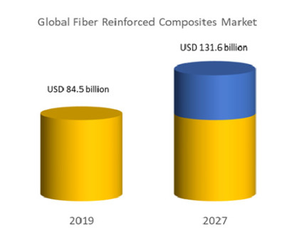
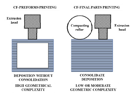
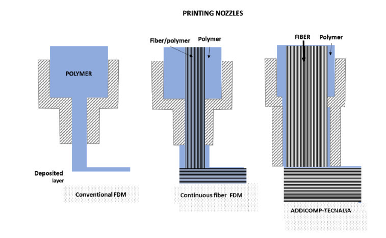
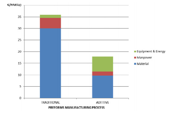
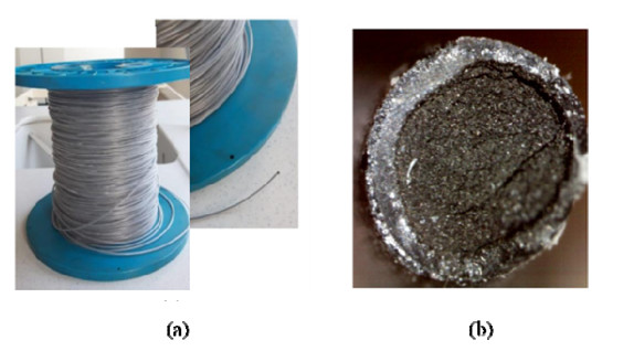
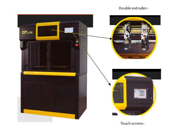
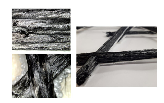
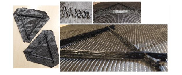
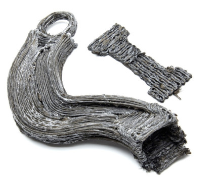
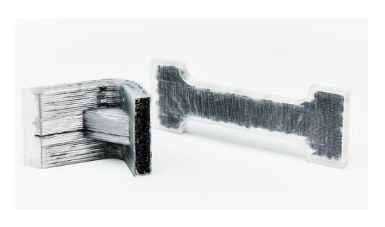
The composites industry is present in practically all industrial sectors with an annual growth rate of 5%. Its contribution to the priority "light-weighting" driver in the transport sector is key. The efficiency of the industry is made possible by the evolution of manufacturing processes that also improve the performance of the products obtained. For example, out-of-autoclave (OOA) processes can obtain high-performance composites such as those obtained by the autoclave process at lower costs. A key aspect in the development of this type of process is the preforming of continuous fibre reinforcements, which can achieve high fibre percentages while facilitating processing. Manufacturing these preforms currently requires multiple steps, equipment and tooling. TECNALIA's work developing the ADDICOMP technology, an alternative preform manufacturing method using an additive process based on Fused Deposition Modelling (FDM) is detailed in this article. This development is patented by Tecnalia and was conducted in 2 phases: (a) development of continuous fibre filaments coated with polymeric material and printable by FDM and (b) fine-tuning of FDM technology to print filaments with a very high content of continuous fibre.
Citation: M. A. Mendizabal, Maitane Garcia, Luis Palenzuela, Enrique Hernández. Obtaining preforms by additive fused deposition modelling (FDM) extrusion technology for the manufacture of high-performance composites[J]. AIMS Materials Science, 2022, 9(3): 481-497. doi: 10.3934/matersci.2022028
The composites industry is present in practically all industrial sectors with an annual growth rate of 5%. Its contribution to the priority "light-weighting" driver in the transport sector is key. The efficiency of the industry is made possible by the evolution of manufacturing processes that also improve the performance of the products obtained. For example, out-of-autoclave (OOA) processes can obtain high-performance composites such as those obtained by the autoclave process at lower costs. A key aspect in the development of this type of process is the preforming of continuous fibre reinforcements, which can achieve high fibre percentages while facilitating processing. Manufacturing these preforms currently requires multiple steps, equipment and tooling. TECNALIA's work developing the ADDICOMP technology, an alternative preform manufacturing method using an additive process based on Fused Deposition Modelling (FDM) is detailed in this article. This development is patented by Tecnalia and was conducted in 2 phases: (a) development of continuous fibre filaments coated with polymeric material and printable by FDM and (b) fine-tuning of FDM technology to print filaments with a very high content of continuous fibre.

| [1] | Mutel F (2017) Trends and opportunities in the Composites industry. XXIII Technical Conference CEP Composites. Available from: https://www.interempresas.net/Plastico/Articulos/189333-Los-composites-ganan-terreno-en-sectores-industriales-muy-diversos.html. |
| [2] | The World's Largest Market Research Store, Fiber reinforced composites market by fiber type, resin type and end-user industry: Global opportunity analysis and industry forecast, 2020-2027, 2021. Available from: https://www.researchandmarkets.com/reports/5321542/fiber-reinforced-composites-market-by-fiber-type. |
| [3] |
Ngo TD, Kashani A, Imbalzano G, et al. (2018) Additive manufacturing (3D printing): A review of materials, methods, applications and challenges. Compos Part B-Eng 143: 172-196. https://doi.org/10.1016/j.compositesb.2018.02.012 doi: 10.1016/j.compositesb.2018.02.012

|
| [4] | Mafel A (2021) Introduction to the additive manufacturing of fibre-reinforced composite. JEC Compos Mag, 6-13. |
| [5] | Gardiner G, The evolution of additive composites, CompositesWord, 2021. Available from: https://www.compositesworld.com/articles/the-evolution-of-additive-composites. |
| [6] |
Roan Eagle IN, Yodo N (2021) A review on filament materials for fused filament fabrication. JMMP 5: 69. https://doi.org/10.3390/jmmp5030069 doi: 10.3390/jmmp5030069
|
| [7] | Gardiner G, Mason H, 3D printing with continuous fiber: A landscape, CompositesWord, 2020. Available from: https://www.compositesworld.com/articles/3d-printing-with-continuous-fiber-a-landscape. |
| [8] | Gardiner G, The evolution of additive composites, CompositesWord, 2021. Available from: https://www.compositesworld.com/articles/the-evolution-of-additive-composites. |
| [9] | Gardiner G, Compression RTM for production of future aerostructures, CompositesWord, 2020. Available from: https://www.compositesworld.com/articles/compression-rtm-for-production-of-future-aerostructures. |
| [10] | Maitane G, Mendizabal M, Ollo EO, et al. (2019) Method for additive manufacturing of a preform. European Patent 3827967A1. Available from: https://www.patentguru.com/EP3827967A1. |
| [11] | Gayoso J, Harysmendi I, Mezzacasa R, et al. (2017) Development of preforming and RTM processes for highly integrated structures. Mater Comp 2: 69-74. Available from: https://revista.aemac.org/materiales-compuestos/article/view/149. |
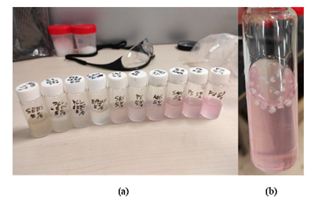
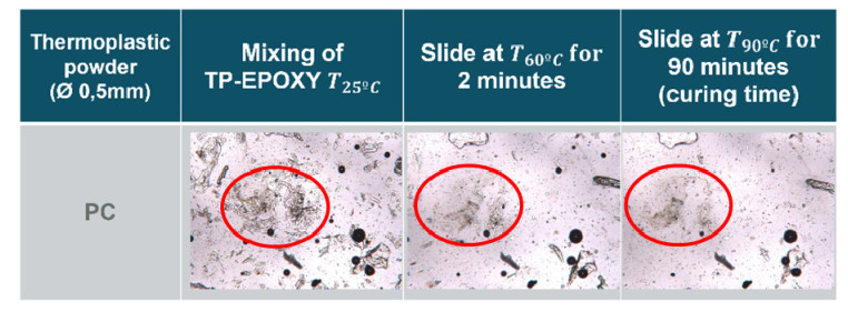
| [12] | Deng S, Djukic L, Paton R, et al. (2015). Thermoplastic-epoxy interactions and their potential applications in joining composite structures-A review. Compos Part A-Appl S 68: 121-132. https://doi.org/10.1016/j.compositesa.2014.09.027 |
| [13] |
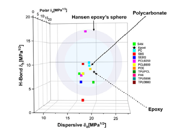
Launay H, Hansen CM, Almdal, K (2007) Hansen solubility parameters for a carbon fiber/epoxy composite. Carbon 45: 2859-2865. https://doi.org/10.1016/j.carbon.2007.10.011 doi: 10.1016/j.carbon.2007.10.011
|
| [14] |
Naffakh M, Dumon M, Gérard JF (2006) Study of a reactive epoxy-amine resin enabling in situ dissolution of thermoplastic films during resin transfer moulding for toughening composites. Compos Sci Technol 66: 1376-1384. https://doi.org/10.1016/j.compscitech.2005.09.007 doi: 10.1016/j.compscitech.2005.09.007
|
| [15] | Hansen CM (2007) Hansen Solubility Parameters: a User's Handbook, CRC press. https://doi.org/10.1201/9781420006834 |
| [16] | Van Krevelen DW, Te Nijenhuis K (2009) Properties of Polymers: Their Correlation with Chemical Structure; Their Numerical Estimation and Prediction from Additive Group Contributions, Elsevier. |
| [17] |
de los Ríos MD, Ramos EH (2020) Determination of the Hansen solubility parameters and the Hansen sphere radius with the aid of the solver add-in of Microsoft Excel. SN Appl Sci 2: 1-7. https://doi.org/10.1007/s42452-020-2512-y doi: 10.1007/s42452-020-2512-y
|
| [18] |
Zanjani JSM, Baran I, Akkerman R (2020) Characterization of interdiffusion mechanisms during co-bonding of unsaturated polyester resin to thermoplastics with different thermodynamic affinities. Polymer 209: 122991. DOI:10.1016/j.polymer.2020.122991 doi: 10.1016/j.polymer.2020.122991
|
Figures(14)

M. A. Mendizabal, Maitane Garcia, Luis Palenzuela, Enrique Hernández. Obtaining preforms by additive fused deposition modelling (FDM) extrusion technology for the manufacture of high-performance composites[J]. AIMS Materials Science, 2022, 9(3): 481-497. doi: 10.3934/matersci.2022028


 DownLoad: