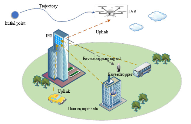
The integration of unmanned aerial vehicle (UAV) networks with intelligent reflecting surface (IRS) technology offers a promising solution to enhance wireless communication by dynamically altering signal propagation. This study addresses the challenge of maximizing system energy efficiency (EE) in IRS-assisted UAV networks. The primary objective is to optimize power allocation and IRS reflection design to achieve this goal. To tackle the optimization problem, we employ a block coordinate descent (BCD) method, decomposing it into three subproblems: phase shift optimization, power allocation, and trajectory planning. These subproblems are iteratively solved using an improved particle swarm optimization (PSO) algorithm. Simulation results demonstrate that the proposed PSO algorithm effectively plans high-quality UAV trajectories in complex environments, significantly enhancing EE. The findings suggest that the IRS-assisted UAV model outperforms traditional UAV models, offering substantial improvements in wireless communication quality and EE.
Citation: Shuang Zhang, Songwen Gu, Yucong Zhou, Lei Shi, Huilong Jin. Energy efficient resource allocation of IRS-Assisted UAV network[J]. Electronic Research Archive, 2024, 32(7): 4753-4771. doi: 10.3934/era.2024217
The integration of unmanned aerial vehicle (UAV) networks with intelligent reflecting surface (IRS) technology offers a promising solution to enhance wireless communication by dynamically altering signal propagation. This study addresses the challenge of maximizing system energy efficiency (EE) in IRS-assisted UAV networks. The primary objective is to optimize power allocation and IRS reflection design to achieve this goal. To tackle the optimization problem, we employ a block coordinate descent (BCD) method, decomposing it into three subproblems: phase shift optimization, power allocation, and trajectory planning. These subproblems are iteratively solved using an improved particle swarm optimization (PSO) algorithm. Simulation results demonstrate that the proposed PSO algorithm effectively plans high-quality UAV trajectories in complex environments, significantly enhancing EE. The findings suggest that the IRS-assisted UAV model outperforms traditional UAV models, offering substantial improvements in wireless communication quality and EE.

| [1] |
A. Sonny, S. R. Yeduri, L. R. Cenkeramaddi, Autonomous UAV path planning using modified PSO for UAV-assisted wireless networks, IEEE Access, 2023 (2023). https://doi.org/10.1109/ACCESS.2023.3293203 doi: 10.1109/ACCESS.2023.3293203

|
| [2] |
C. Pan, G. Zhou, K. Zhi, S. Hong, T. Wu, Y. Pan, et al., An overview of signal processing techniques for RIS/IRS-aided wireless systems, IEEE J. Sel. Top. Signal Process., 16 (2022), 883–917. https://doi.org/10.1109/JSTSP.2022.3195671 doi: 10.1109/JSTSP.2022.3195671
|
| [3] |
C. You, Z. Kang, Y. Zeng, R. Zhang, Enabling smart reflection in integrated air-ground wireless network: IRS meets UAV, IEEE Wireless Commun., 28 (2021), 138–144. https://doi.org/10.1109/MWC.001.2100148 doi: 10.1109/MWC.001.2100148
|
| [4] |
A. Mahmoud, S. Muhaidat, P. C. Sofotasios, I. Abualhaol, O. A. Dobre, H. Yanikomeroglu, et al., Intelligent reflecting surfaces assisted UAV communications for IoT networks: Performance analysis, IEEE Trans. Green Commun. Networking, 5 (2022), 1029–1040. https://doi.org/10.1109/TGCN.2021.3068739 doi: 10.1109/TGCN.2021.3068739
|
| [5] |
X. Liu, Y. Liu, Y. Chen, Machine learning empowered trajectory and passive beamforming design in UAV-RIS wireless networks, IEEE J. Sel. Areas Commun., 39 (2021). https://doi.org/10.1109/JSAC.2020.3041401 doi: 10.1109/JSAC.2020.3041401
|
| [6] |
W. Yu, J. Liu, J. Zhou, A novel sparrow particle swarm algorithm (SPSA) for unmanned aerial vehicle path planning, Sci. Program., 2021 (2021), 1–15. https://doi.org/10.1155/2021/5158304 doi: 10.1155/2021/5158304
|
| [7] |
X. Zhou, F. Gao, X. Fang, Z. Lan, Improved bat algorithm for UAV path planning in three-dimensional space, IEEE Access, 9 (2021), 20100–20116. https://doi.org/10.1109/ACCESS.2021.3054179 doi: 10.1109/ACCESS.2021.3054179
|
| [8] | Q. Deng, Integrated planning of UAV 3D trajectory based on ant colony algorithm, in Journal of Physics: Conference Series, 2330 (2022). https://doi.org/10.1088/1742-6596/2330/1/012009 |
| [9] |
Y. Su, X. Pang, S. Chen, X. Jiang, N. Zhao, F. R. Yu, Spectrum and energy efficiency optimization in IRS-assisted UAV networks, IEEE Trans. Commun., 70 (2022), 6489–6502. https://doi.org/10.1109/TCOMM.2022.3201122 doi: 10.1109/TCOMM.2022.3201122
|
| [10] |
X. Song, Y. Zhao, Z. Wu, Z. Yang, J. Tang, Joint trajectory and communication design for irs-assisted uav networks, IEEE Wireless Commun. Lett., 11 (2022), 1538–1542. https://doi.org/10.1109/LWC.2022.3179028 doi: 10.1109/LWC.2022.3179028
|
| [11] | H. Long, M. Chen, Z. Yang, Z. Li, B. Wang, X.Yun, et al., Joint trajectory and passive beamforming design for secure UAV networks with RIS, in 2020 IEEE Globecom Workshops, (2020), 1–6. https://doi.org/10.1109/GCWkshps50303.2020.9367542 |
| [12] |
Z. Ji, W. Yang, X. Guan, X. Zhao, G. Li, Q. Wu, Trajectory and transmit power optimization for IRS-assisted UAV communication under malicious jamming, IEEE Trans. Veh. Technol., 71 (2022), 11262–11266. https://doi.org/10.1109/TVT.2022.3187092 doi: 10.1109/TVT.2022.3187092
|
| [13] |
X. Mu, Y. Liu, L. Guo, J. Lin, H. V. Poor, Intelligent reflecting surface enhanced multi-UAV NOMA networks, IEEE J. Sel. Areas Commun., 39 (2021), 3051–3066. https://doi.org/10.1109/JSAC.2021.3088679 doi: 10.1109/JSAC.2021.3088679
|
| [14] |
H. Shakhatreh, A. Sawalmeh, A. H. Alenezi, S. Abdel-Razeq, A. Al-Fuqaha, Mobile-IRS assisted next generation UAV communication networks, Comput. Commun., 215 (2024), 51–61. https://doi.org/10.1016/j.comcom.2023.12.025 doi: 10.1016/j.comcom.2023.12.025
|
| [15] |
M. Diamanti, M. Tsampazi, E. E. Tsiropoulou, S. Papavassiliou, Energy efficient multi-user communications aided by reconfigurable intelligent surfaces and UAVs, IEEE International Conference on Smart Computing (SMARTCOMP), (2021), 371–376. https://doi.org/10.1109/SMARTCOMP52413.2021.00075 doi: 10.1109/SMARTCOMP52413.2021.00075
|
| [16] |
X. Zhang, H. Zhang, W. Du, K. Long, A. Nallanathan, IRS empowered UAV wireless communication with resource allocation, reflecting design and trajectory optimization, IEEE Trans. Wireless Commun., 21 (2022), 7867–7880. https://doi.org/10.1109/TWC.2022.3162704 doi: 10.1109/TWC.2022.3162704
|
| [17] |
N. Lin, H. Tang, L. Zhao, S. Wan, A. Hawbani, M. Guizani, A PDDQNLP algorithm for energy efficient computation offloading in UAV-assisted MEC, IEEE Trans. Wireless Commun., 22 (2023), 8876–8890. https://doi.org/10.1109/TWC.2023.3266497 doi: 10.1109/TWC.2023.3266497
|
| [18] |
J. Yu, X. Liu, Y. Gao, C. Zhang, W. Zhang, Deep learning for channel tracking in IRS-assisted UAV communication systems, IEEE Trans. Wireless Commun., 21 (2022), 7711–7722. https://doi.org/10.1109/TWC.2022.3160517 doi: 10.1109/TWC.2022.3160517
|
| [19] |
S. M. M. Abohashish, R. Y. Rizk, E. I. Elsedimy, Trajectory optimization for UAV-assisted relay over 5G networks based on reinforcement learning framework, EURASIP J. Wireless Commun. Networking, 2023 (2023), 55. https://doi.org/10.1186/s13638-023-02268-x doi: 10.1186/s13638-023-02268-x
|
| [20] |
Y. Ullah, M. Roslee, S. M. Mitani, M. Sheraz, F. Ali, A. F. Osman, et al., Reinforcement learning-based unmanned aerial vehicle trajectory planning for ground users' mobility management in heterogeneous networks, J. King Saud Univ. Comput. Inf. Sci., 36 (2024), 102052. https://doi.org/10.1016/j.jksuci.2024.102052 doi: 10.1016/j.jksuci.2024.102052
|
| [21] |
M. Ejaz, J. Gui, M. Asim, M. ElAffendi, C. Fung, A. A. Abd El-Latif, RL-Planner: Reinforcement learning-enabled efficient path planning in multi-UAV MEC systems, IEEE Trans. Network Serv. Manage., 2024 (2024). https://doi.org/10.1109/TNSM.2024.3378677 doi: 10.1109/TNSM.2024.3378677
|
| [22] |
L. Wang, K. Wang, C. Pan, N. Aslam, Joint trajectory and passive beamforming design for intelligent reflecting surface-aided UAV communications: A deep reinforcement learning approach, IEEE Trans. Mobile Comput., 22 (2022), 6543–6553. https://doi.org/10.1109/TMC.2022.3200998 doi: 10.1109/TMC.2022.3200998
|
| [23] |
P. Huang, Y. Wang, K. Wang, Energy-efficient trajectory planning for a multi-UAV-assisted mobile edge computing system, Front. Inf. Technol. Electron. Eng., 21 (2020), 1713–1725. https://doi.org/10.1631/FITEE.2000315 doi: 10.1631/FITEE.2000315
|
| [24] |
K. Zhi, C. Pan, H. Ren, K. K. Chai, M. Elkashlan, Active RIS versus passive RIS: Which is superior with the same power budget?, IEEE Commun. Lett., 26 (2022), 1150–1154. https://doi.org/10.1109/LCOMM.2022.3159525 doi: 10.1109/LCOMM.2022.3159525
|
| [25] |
S. Li, B. Duo, X. Yuan, Y. C. Liang, M. Di Renzo, Reconfigurable intelligent surface assisted UAV communication: Joint trajectory design and passive beamforming, IEEE Wireless Commun. Lett., 9 (2020), 716–720. https://doi.org/10.1109/LWC.2020.2966705 doi: 10.1109/LWC.2020.2966705
|
| [26] |
M. Alzenad, A. El-Keyi, H. Yanikomeroglu, 3-D placement of an unmanned aerial vehicle base station for maximum coverage of users with different QoS requirements, IEEE Wireless Commun. Lett., 7 (2017), 38–41. https://doi.org/10.1109/LWC.2017.2752161 doi: 10.1109/LWC.2017.2752161
|
| [27] | Y. An, Z. Zhang, W. Wu, Study on the UAV trajectory planning route based on the particle group optimization algorithm, in 2022 4th International Conference on Applied Machine Learning (ICAML), (2022), 184–187. https://doi.org/10.1109/ICAML57167.2022.00042 |
| [28] |
L. Li, X. Yang, Inspection path optimization of the agricultural unmanned aerial vehicle based on the improved PSO algorithm, J. Eng. Sci. Technol. Rev., 16 (2023), 38–41. https://doi.org/10.25103/jestr.165.11 doi: 10.25103/jestr.165.11
|
| [29] |
S. Shao, Y. Peng, C. He, Y. Du, Efficient path planning for UAV formation via comprehensively improved particle swarm optimization, ISA Trans., 97 (2020), 415–430. https://doi.org/10.1016/j.isatra.2019.08.018 doi: 10.1016/j.isatra.2019.08.018
|
| [30] | H. Cao, H. Zhang, Z. Liu, Y. Zhou, Y. Wang, UAV path planning based on improved particle swarm algorithm, in 2021 7th International Symposium on Mechatronics and Industrial Informatics (ISMII), IEEE, (2021), 284–287. https://doi.org/10.1109/ISMII52409.2021.00067 |


Figures(4)
Shuang Zhang, Songwen Gu, Yucong Zhou, Lei Shi, Huilong Jin. Energy efficient resource allocation of IRS-Assisted UAV network[J]. Electronic Research Archive, 2024, 32(7): 4753-4771. doi: 10.3934/era.2024217


 DownLoad: