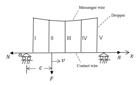
The most essential cause of the fracture of the dropper is the effect of alternating stress for a long time. Therefore, in order to ensure the safe operation of high-speed railways, the influence of moving loads on the stress of a dropper was investigated in this study. Due to a high-voltage catenary system, it is very difficult to measure the moving load. Thus, the uplift displacement measured by some software and hardware devices has been applied to the contact wire instead of the moving load. The response equation for the contact wire has been derived so as to determine the initial and boundary conditions of each dropper. Then it was combined with the equation for vibration analysis of the dropper and the stress of each dropper was calculated by using the finite-difference method based on a written MATLAB program. The results show that the dropper stress, during a certain period goes through two stages of immediate rebound and bending compression when the uplift displacement is large. After the pantograph passes, the vibration of the dropper tends to be smooth; also, dropper stress variation with timecan be described by three stages: immediate rebound, vibration attenuation, and bending compression. In addition, the maximum tensile stress of dropper Ⅳ was the highest. It indicates that dropper Ⅳ was more prone to fracture than other droppers.
Citation: Caizhi Yang, Xinxin Shen, Like Pan, Liming Chen, Fan He. Numerical analysis of dropper stress under a moving load based on the uplift displacement for a high-speed railway[J]. AIMS Mathematics, 2024, 9(3): 6568-6585. doi: 10.3934/math.2024320
The most essential cause of the fracture of the dropper is the effect of alternating stress for a long time. Therefore, in order to ensure the safe operation of high-speed railways, the influence of moving loads on the stress of a dropper was investigated in this study. Due to a high-voltage catenary system, it is very difficult to measure the moving load. Thus, the uplift displacement measured by some software and hardware devices has been applied to the contact wire instead of the moving load. The response equation for the contact wire has been derived so as to determine the initial and boundary conditions of each dropper. Then it was combined with the equation for vibration analysis of the dropper and the stress of each dropper was calculated by using the finite-difference method based on a written MATLAB program. The results show that the dropper stress, during a certain period goes through two stages of immediate rebound and bending compression when the uplift displacement is large. After the pantograph passes, the vibration of the dropper tends to be smooth; also, dropper stress variation with timecan be described by three stages: immediate rebound, vibration attenuation, and bending compression. In addition, the maximum tensile stress of dropper Ⅳ was the highest. It indicates that dropper Ⅳ was more prone to fracture than other droppers.

| [1] |
J. Ruan, H. B. Yuan, H. M. Li, H. Y. Xu, Design and application of vibratory fatigue test rig for high speed railway OCS dropper, China Railway, 2020 (2020), 117–122. https://doi.org/10.19549/j.issn.1001-683x.2020.08.117 doi: 10.19549/j.issn.1001-683x.2020.08.117

|
| [2] |
L. K. Pan, L. M. Chen, H. B. Zhang, C. Xu, C. Z. Yang, T. Xing, Research on vibration fatigue test method and device of integrated dropper, Electr. Railway, 31 (2020), 73–76. https://doi.org/10.19587/j.cnki.1007-936x.2020z2.017 doi: 10.19587/j.cnki.1007-936x.2020z2.017
|
| [3] |
P. H. Peng, L. M. Chen, W. Wang, F. He, The effect of frequency and amplitude of dropper on its fatigue life, J. Railway Sci. Eng., 16 (2019), 471–477. https://doi.org/10.19713/j.cnki.43-1423/u.2019.02.025 doi: 10.19713/j.cnki.43-1423/u.2019.02.025
|
| [4] |
X. Li, W. Z. Liu, C. Sun, J. H. Yi, M. Xu, Study on current collection characteristics of catenary based on new type of dropper, Railway Stand. Design, 65 (2021), 128–131. https://doi.org/10.13238/j.issn.1004-2954.202001060004 doi: 10.13238/j.issn.1004-2954.202001060004
|
| [5] |
W. H. Zhang, G. M. Mei, X. J. Wu, L. Q. Chen, A study on dynamic behaviour of pantographs by using hybrid simulation method, Proc. I. Mech. Eng. Part F, 219 (2005), 189–199. https://doi.org/10.1243/095440905X8880 doi: 10.1243/095440905X8880
|
| [6] |
H. Zhao, X. H. Xiao, G. F. Qi, H. Y. Xu, H. M. Li, Analysis of fatigue life of catenary dropper for high-speed railway, Eng. J. Wuhan Univ., 52 (2019), 351–357. https://doi.org/10.14188/j.1671-8844.2019-04-011 doi: 10.14188/j.1671-8844.2019-04-011
|
| [7] | Q. Zhang, Research on fatigue characteristics of catenary droppers of high-speed railway, Shijiazhuang: Shijiazhuang Tiedao University, 2023. https://doi.org/10.27334/d.cnki.gstdy.2022.000442 |
| [8] | D. F. Chen, Analysis on the operation characteristics of the integral dropper of high-speed rail catenary and discussion on countermeasures, Beijing: China Academy of Railway Sciences, 2020. https://doi.org/10.27369/d.cnki.gtdky.2020.000049 |
| [9] |
L. M. Chen, J. Sun, L. K. Pan, F. He, Analysis of dropper stress in a catenary system for a high-speed railway, Math. Probl. Eng., 2022 (2022), 1–7. https://doi.org/10.1155/2022/9663767 doi: 10.1155/2022/9663767
|
| [10] |
F. He, D. D. Guo, The effects of load location on dropper stress in a catenary system for a high-speed railway, Math. Probl. Eng., 2020 (2020), 1–10. https://doi.org/10.1155/2020/7986141 doi: 10.1155/2020/7986141
|
| [11] |
L. M. Chen, P. H. Peng, F. He, Fatigue life analysis of dropper used in pantograph-catenary system of high-speed railway, Adv. Mech. Eng., 10 (2018), 1–10. https://doi.org/10.1177/1687814018776135 doi: 10.1177/1687814018776135
|
| [12] | Y. Zhong, A new approach to desired contact force between pantograph and overhead contact line system based on sliding electrical contact fundamental mechanism, Cheng Du: Southwest Jiaotong University, 2020. https://doi.org/10.27414/d.cnki.gxnju.2020.002536 |
| [13] |
J. B. Guo, S. P. Yang, G. S. Gao, Study on active control of high-speed-train pantographs, J. China Railway Soc., 26 (2004), 41–45. https://doi.org/10.3321/j.issn:1001-8360.2004.04.009 doi: 10.3321/j.issn:1001-8360.2004.04.009
|
| [14] |
L. M. Chen, Study on dynamic force of integral dropper of catenary under action of high-speed pantograph, China Railway Sci., 39 (2018), 86–92. https://doi.org/10.3969/j.issn.1001-4632.2018.03.12 doi: 10.3969/j.issn.1001-4632.2018.03.12
|
| [15] |
S. G. Zhang, A finite difference method for second order ordinary differential equation of initial-value problem, J. Chongqing Univ. Tech., 26 (2012), 110–112. https://doi.org/10.3969/j.issn.1674-8425-B.2012.08.023 doi: 10.3969/j.issn.1674-8425-B.2012.08.023
|
| [16] | A. G. Costello, Theory of wire rope, New York: Springer, 1997. https://doi.org/10.1007/978-1-4612-1970-5 |
| [17] |
Z. G. Yu, Z. R. Ge, Z. S. Niu, Z. Y. Zhu, Discussion on causes of failures and optimized schemes for OCS integrated droppers for high speed railway, Electr. Railway, 31 (2020), 10–14. https://doi.org/10.19587/j.cnki.1007-936x.2020.01.003 doi: 10.19587/j.cnki.1007-936x.2020.01.003
|
| [18] | H. Li, M. Yazdi, Advanced decision-making methods and applications in system safety and reliability problems, Switzerland: Springer, 2022. https://doi.org/10.1007/978-3-031-07430-1 |


Figures(10) / Tables(2)

Caizhi Yang, Xinxin Shen, Like Pan, Liming Chen, Fan He. Numerical analysis of dropper stress under a moving load based on the uplift displacement for a high-speed railway[J]. AIMS Mathematics, 2024, 9(3): 6568-6585. doi: 10.3934/math.2024320


 DownLoad: