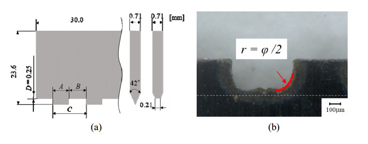
This study reveals the bending formability of a polypropylene (PP) sheet indented by a perforation blade when changing the pitch of the dashed-ruled line and the indentation depth. Creasing is a folding method of a carton sheet in which a score (called as a ruled line) is made at the bent portion. When making a creased line on a resin sheet, the scored sheet thickness decreases by applying half cutting or creasing (pressing) at the bent portion to make it easier to fold. To smoothly process a folding line on the resin sheet, a dashed line using a perforation blade is sometimes considered. The pitch length of the dashed line, and its nicked (uncut) length, affect the crease bending characteristics of the resin sheet scored by the perforation blade. However, only a limited number of studies have analyzed the dashed line bending moment response. In this study, to clarify the bending formability of a 0.5-mm-thick PP sheet indented by a developed perforation blade, first, the influence of the perforation pitch length on the crease bending characteristics of a scored PP sheet was investigated from a 0.5-mm fine pitch up to an 8-mm commercially sold pitch with a cutting-to-pitch length ratio of 50%. Second, the nicked zone depth against the cutting tip was set as 50% of the 0.5-mm thickness of the PP sheet. Furthermore, it was revealed that burrs (wedged bottom) in the cut part of the perforated (dashed) line affected the bending moment resistance in the folding process of the scored PP sheet, when changing the indentation depth of the perforation blade.
Citation: Shigeru Nagasawa, Tomoki Hosokawa. Effects of pitch length of perforation on the crease bending characteristics of a polypropylene sheet subjected to indentation of a perforation blade[J]. AIMS Materials Science, 2022, 9(6): 808-834. doi: 10.3934/matersci.2022050
This study reveals the bending formability of a polypropylene (PP) sheet indented by a perforation blade when changing the pitch of the dashed-ruled line and the indentation depth. Creasing is a folding method of a carton sheet in which a score (called as a ruled line) is made at the bent portion. When making a creased line on a resin sheet, the scored sheet thickness decreases by applying half cutting or creasing (pressing) at the bent portion to make it easier to fold. To smoothly process a folding line on the resin sheet, a dashed line using a perforation blade is sometimes considered. The pitch length of the dashed line, and its nicked (uncut) length, affect the crease bending characteristics of the resin sheet scored by the perforation blade. However, only a limited number of studies have analyzed the dashed line bending moment response. In this study, to clarify the bending formability of a 0.5-mm-thick PP sheet indented by a developed perforation blade, first, the influence of the perforation pitch length on the crease bending characteristics of a scored PP sheet was investigated from a 0.5-mm fine pitch up to an 8-mm commercially sold pitch with a cutting-to-pitch length ratio of 50%. Second, the nicked zone depth against the cutting tip was set as 50% of the 0.5-mm thickness of the PP sheet. Furthermore, it was revealed that burrs (wedged bottom) in the cut part of the perforated (dashed) line affected the bending moment resistance in the folding process of the scored PP sheet, when changing the indentation depth of the perforation blade.

| [1] | Hine DJ (1959) Testing boxboard creasing. Modern Packaging 8: 122–128. |
| [2] |
Beex LAA, Peelings RHJ (2009) An experimental and computational study of creasing of paperboard. Int J Solids Struct 46: 4192–4207. https://doi.org/10.1016/j.ijsolstr.2009.08.012 doi: 10.1016/j.ijsolstr.2009.08.012

|
| [3] | Kirwan JM (2013) Handbook of Paper and Paperboard Packaging Technology, 2 Eds., Wiley-Blackwell, 280–292. https://doi.org/10.1002/9781118470930 |
| [4] | Hashimoto T (2004) Processing technology of transparent packaging box and related problems. Carton Box 23: 44–45 (in Japanese). |
| [5] |
Nagasawa S (2016) Cutting and bending of plastics sheet. J JSTP 57: 867–872. https://doi.org/10.9773/sosei.57.867 doi: 10.9773/sosei.57.867
|
| [6] | Carey KB (1992) Creasing: Turning failure into success. Packaging Product 1: 1–20. |
| [7] |
Carlsson L, De Ruvo A, Fellers C (1983) Bending properties of creased zones of paperboard related to interlaminar defects. J Mater Sci 18: 1365–1373. https://doi.org/10.1007/BF01111956 doi: 10.1007/BF01111956
|
| [8] |
Nagasawa S, Nasruddin M, Shiga Y (2011) Bending moment characteristics on repeated folding motion of coated paperboard scored by round-edge knife. J Adv Mech Des Syst 5: 385–394. https://doi.org/10.1299/jamdsm.5.385 doi: 10.1299/jamdsm.5.385
|
| [9] | Nagasawa S, Fukuzawa Y, Murayama M, et al. (2016) Mechanics and Technology of Form Cutting for Paperboard-like Materials Processing, Solar publishing, 101–122 (in Japanese). |
| [10] | Packaging Europe (2017) Marbach: digital zone levelling on the road to success. Available from: https://packagingeurope.com/marbach-digital-zone-levelling-on-the-road-to-success/3409.article. |
| [11] | Gahleitner M, Paulik C (2014) Polypropylene, Ullmann's Encyclopedia of Industrial Chemistry, Weinheim: Wiley-VCH, 1–44. https://doi.org/10.1002/14356007.o21_o04.pub2. |
| [12] | Crawford RJ (1999) Plastics Engineering, 3 Eds., Burlington: Elsevier Butterworth-Heinemann, 1–40. |
| [13] | Ishihara H (2010) Fundamental and application of plastics films, Converting Technical Institute, Tokyo, 33–52 (in Japanese). |
| [14] |
Okuda S, Choi WS (1981) Mechanism of cutting fracture of polypropylene by impact on wedge-shaped target. J Chem Eng Jpn 14: 149–153. Available from: https://doi.org/10.1252/jcej.14.149. doi: 10.1252/jcej.14.149
|
| [15] |
Bauer W, Wüstenberg D (2002) Fracture behavior of polypropylene under dynamic cutting and shearing action in granulators. Chem Eng Technol 25: 1047–1051. https://doi.org/10.1002/1521-4125(20021105)25:11<1047::AID-CEAT1047>3.0.CO;2-6 doi: 10.1002/1521-4125(20021105)25:11<1047::AID-CEAT1047>3.0.CO;2-6
|
| [16] | Yamamoto A, Singprayoon S, Nagasawa S, et al. (2017) Bending behavior of polypropylene sheet subjected to two-line wedge indentation. Trans on GIGAKU 4: 04003/1-9. Available from: https://lib.nagaokaut.ac.jp/gigaku-press/ToG/transactions.files/TGVol4-1.pdf. |
| [17] | American Micro Industries Inc., 2021. Perforation die cutting. Available from: https://www.americanmicroinc.com/die-cutting/perforation-die-cutting/. |
| [18] | Zimmer G (2005) Scoring/creasing plastics, Cutting Edge 23: 1–4. Available from: http://www.iadd.org/pages/samples/CE23-01A.htm. |
| [19] | Katayama Steel Rule Die Inc., 2022. Crease stress tester CST-J1, Available from: http://diemex.com/sale/cst.html. |
| [20] | Kudo H (1968) Plasticity, Morikita publishing, 16–23 (in Japanese). |
| [21] | Teng JG (1998) Plastic buckling of transition ringbeams in steel silos and tanks, In: Usami T, Itoh Y, Stability and Ductility of Steel Structures, Elsevier, 265–276. Available from: https://doi.org/10.1016/B978-008043320-2/50024-1. |
| [22] | Engineers Edge, 2022. Plastic Section modulus. Available from: https://www.engineersedge.com/material_science/section_modulus_12893.htm. |
| [23] | Timoshenko S (1955) Part 1: Elementary theory and problems, Strength of Materials, Tokyo-tosyo publishing, 144–145. |
| [24] | James MG (2001) Mechanics of Materials, Brooks/Cole, 615–646. |


Figures(26) / Tables(2)

Shigeru Nagasawa, Tomoki Hosokawa. Effects of pitch length of perforation on the crease bending characteristics of a polypropylene sheet subjected to indentation of a perforation blade[J]. AIMS Materials Science, 2022, 9(6): 808-834. doi: 10.3934/matersci.2022050


 DownLoad: