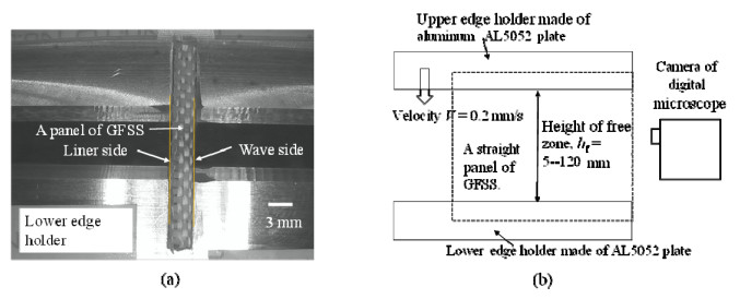
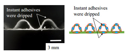
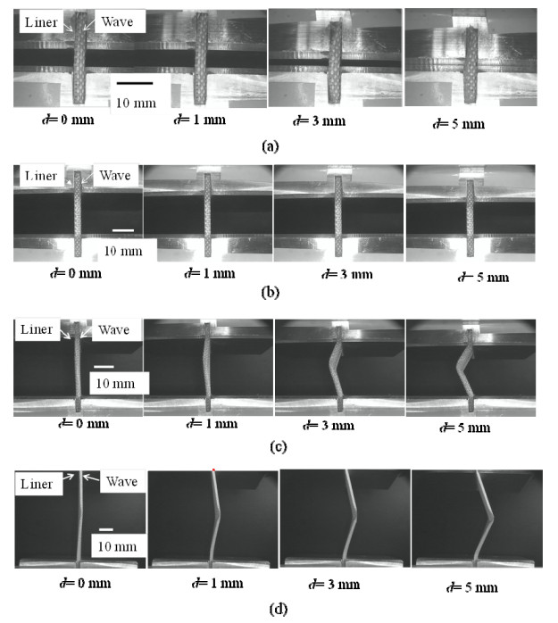
This work aims to reveal the in-plane-compressive characteristics of Glass Fibre based single face corrugated Structure Sheet (GFSS) by developing a loading holder of the both ends of the panel of GFSS in the direction of the cross machine direction. A grooved end-support device was developed and exmined. In order to set stably and quickly a straight panel of GFSS on the compressive-testing apparatus, the width and the depth of the holder's groove were varied against the geometrical size of the panel, and the stability and reproducibility of compressive deformation of the panel was experimentally investigated. When changing the height of the panel and reinforcing the both ends of the panel by dipping instant adhesives, the deformation behavior and the buckling strength was characterized in three modes: a short height crushing without lateral deflection, a small lateral deflection mode as the intermediate state, and a triangle-like folding as a long height crushing.
Citation: Songtam Laosuwan, Shigeru Nagasawa. Development of compressive testing device for glass fiber based single face corrugated structure sheet, and estimation of buckling strength of straight panel of that structure sheet[J]. AIMS Materials Science, 2021, 8(6): 881-898. doi: 10.3934/matersci.2021054
This work aims to reveal the in-plane-compressive characteristics of Glass Fibre based single face corrugated Structure Sheet (GFSS) by developing a loading holder of the both ends of the panel of GFSS in the direction of the cross machine direction. A grooved end-support device was developed and exmined. In order to set stably and quickly a straight panel of GFSS on the compressive-testing apparatus, the width and the depth of the holder's groove were varied against the geometrical size of the panel, and the stability and reproducibility of compressive deformation of the panel was experimentally investigated. When changing the height of the panel and reinforcing the both ends of the panel by dipping instant adhesives, the deformation behavior and the buckling strength was characterized in three modes: a short height crushing without lateral deflection, a small lateral deflection mode as the intermediate state, and a triangle-like folding as a long height crushing.

| [1] | Kubo corporation, Glass fibre based structural sheet, 2017. Available from: http://www.kubo-co.net/. |
| [2] | Kirwan MJ (2013) Corrugated fiberboard packaging, Handbook of Paper and Paperboard Packaging Technology, 2 Eds., John Wiley & Sons, 313–321. |
| [3] | Jonson G (1999) Corrugated Board Packaging, 2 Eds., Leather head: Pira International, 145–159. |
| [4] | Lubin G (1982) Characterization of corrugated board, Handbook of Composite, Springer, Boston, MA, 145–149. |
| [5] | Mark RE, Habeger C, Borch J, et al. (2002) Characterization of corrugated board, Handbook of Physical Testing of Paper, 2 Eds., CRC Press, 1: 571–574. |
| [6] | Twede D, Selke SM, Kamdem D, et al. (2015) Single face, Cartons, Crafts and Corrugated Board: Handbook of Paper and Wood Packaging Technology, DEStech publication, 460–464. |
| [7] | Twede D, Selke SEM, Kamdem D, et al. (2015) Cartons, Crafts and Corrugated Board: Handbook of Paper and Wood Packaging Technology, DEStech publication, 250–252. |
| [8] | Bronkhorst CA, Keith AB (2002) Deformation and failure behaviour of paper (Edge wise crush test), In: Mark RE, Habeger C, Borch J, et al., Handbook of Physical Testing of Paper, 2 Eds., CRC Press, 1: 401–409. |
| [9] |
Nagasawa S, Kudo H, Songtam L, et al. (2017) Tensile characteristics of glass fiber based single face board. Procedia Eng 207: 78–83. doi: 10.1016/j.proeng.2017.10.738

|
| [10] |
Laosuwan S, Nagasawa S, Umemoto K (2020) Development of tensile fixture with corrugated structure sheet and estimation of tensile strength of glass fibre fabrics based single face corrugated structure sheet. AIMS Mater Sci 7: 75–92. doi: 10.3934/matersci.2020.1.75
|
| [11] |
Matsushima S, Okuda T, Miyauchi O, et al. (1982) Strength of tensile deformation for corrugated fibre board. Japan TAPPI J 36: 377–387. doi: 10.2524/jtappij.36.377
|
| [12] | Wahab N, Arafah A, Fukuzawa Y et al. (2016) Estimation of corrugated cardboard strength using tensile test, In: MFB Abdollah, MAB Salim, TB Tuan, Proceeding of Mechanical Engineering Research Day 2016, Melaka: Centre for Advanced Research on Energy. |
| [13] |
Cox HL (1952) The elasticity and strength of paper and other fibrous materials. Br J Appl Phys 3: 72–79. doi: 10.1088/0508-3443/3/3/302
|
| [14] | T glass, Niitobo corporation, 2019. Available from: https://www.nittobo.co.jp/business/glassfibre/sp_material/t-glass.htm. |
| [15] | Loewenstein KL (1973) The Manufacturing Technology of Continuous Glass Fibres, 2–94, Elsevier Scientific. |
| [16] | Loewenstein KL (1975) The manufacture of continuous glass fibres. Platinum Met Rev 19: 84–87 |
| [17] | Popil RE (2017) Bending stiffness of corrugated board, Physical Testing of Paper, UK: Smithers Pira, 67–77. |
| [18] | Timoshenko S (1955) Elementary theory and problems, Strength of materials, 3 Eds., D. Van Nostrand Company, 252–266. |
| [19] |
Mihara Y, Kobayashi T, Fujii F (2011) Postbuckling analyses of elastic cylinderical shells under axial compression. Trans JSME 77: 582–589. doi: 10.1299/kikaia.77.582
|
Figures(18) / Tables(2)

Songtam Laosuwan, Shigeru Nagasawa. Development of compressive testing device for glass fiber based single face corrugated structure sheet, and estimation of buckling strength of straight panel of that structure sheet[J]. AIMS Materials Science, 2021, 8(6): 881-898. doi: 10.3934/matersci.2021054


 DownLoad: