The exposed platform is the main component of precision instruments such as pyrotechnic separation devices and load adapters, and its dynamic response characteristics are a key factor affecting the stability of aircraft. When the pyrotechnic separation device explodes, the exposed platform will be subjected to high-frequency, transient and high-order pyrotechnic impacts. High order pyrotechnic impacts can easily cause damage to sensitive components in onboard equipment, resulting in incalculable losses. Filling the honeycomb core cavity inside the exposed platform with a flexible boundary particle damper can effectively attenuate the pyrotechnic impact load after experiencing a large number of discontinuous structures. A numerical model of a flexible boundary particle damper and an exposed platform honeycomb panel was established through the coupling of discrete element and multi body dynamics. The effects of particle material, particle size, filling rate and flexible boundary film thickness on the impact reduction performance of the flexible boundary particle damper were analyzed, and the optimal characteristic parameters of the flexible boundary particle damper were obtained. The impact test was conducted on the honeycomb panel of the exposed platform using a light gas gun impact experiment, verifying the impact reduction effect of the flexible boundary particle damper and the accuracy of the numerical model. Finally, a pyrotechnic impact experiment was conducted on the exposed platform honeycomb panel with the optimal parameter flexible boundary particle damper. The experimental results showed that the impact reduction effect of the flexible boundary particle damper with this parameter reached 55.52%.
Citation: Dike Hu, Hua Wang, Zijie Huang, Wangqiang Xiao. Research on impact reduction of flexible boundary particle damping honeycomb plate based on discrete element multi body dynamics coupling[J]. Electronic Research Archive, 2023, 31(10): 6303-6326. doi: 10.3934/era.2023319
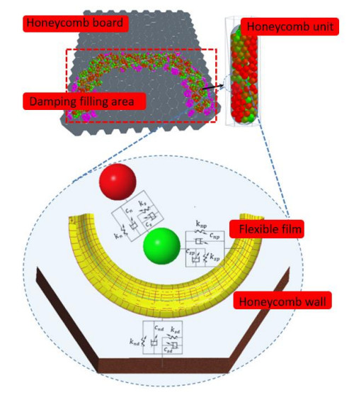
The exposed platform is the main component of precision instruments such as pyrotechnic separation devices and load adapters, and its dynamic response characteristics are a key factor affecting the stability of aircraft. When the pyrotechnic separation device explodes, the exposed platform will be subjected to high-frequency, transient and high-order pyrotechnic impacts. High order pyrotechnic impacts can easily cause damage to sensitive components in onboard equipment, resulting in incalculable losses. Filling the honeycomb core cavity inside the exposed platform with a flexible boundary particle damper can effectively attenuate the pyrotechnic impact load after experiencing a large number of discontinuous structures. A numerical model of a flexible boundary particle damper and an exposed platform honeycomb panel was established through the coupling of discrete element and multi body dynamics. The effects of particle material, particle size, filling rate and flexible boundary film thickness on the impact reduction performance of the flexible boundary particle damper were analyzed, and the optimal characteristic parameters of the flexible boundary particle damper were obtained. The impact test was conducted on the honeycomb panel of the exposed platform using a light gas gun impact experiment, verifying the impact reduction effect of the flexible boundary particle damper and the accuracy of the numerical model. Finally, a pyrotechnic impact experiment was conducted on the exposed platform honeycomb panel with the optimal parameter flexible boundary particle damper. The experimental results showed that the impact reduction effect of the flexible boundary particle damper with this parameter reached 55.52%.

| [1] |
J. Lee, D. H. Hwang, J. H. Han, Study on Pyroshock propagation through plates with joints and washers, Aerosp. Sci. Technol., 97 (2018), 441–458. https://doi.org/10.1016/j.ast.2018.05.057 doi: 10.1016/j.ast.2018.05.057

|
| [2] |
H. Zhao, W. Liu, J. Ding, Y. Sun, X. Li, Y. Liu, Numerical study on separation shock characteristics of pyrotechnic separation nuts, Acta Astronaut., 151 (2018), 893–903. https://doi.org/10.1016/j.actaastro.2018.07.040 doi: 10.1016/j.actaastro.2018.07.040
|
| [3] |
J. Ding, H. Zhao, J. Wang, Y. Sun, Z. Chen, Numerical and experimental investigation on the shock mitigation of satellite-rocket separation, Aerosp. Sci. Technol., 96 (2020), 105538. https://doi.org/10.1016/j.ast.2019.105538 doi: 10.1016/j.ast.2019.105538
|
| [4] |
D. H. Hwang, J. H. Han, J. Lee, Y. J. Lee, D. Kim, A mathematical model for the separation behavior of a split type low-shock separation bolt, Acta Astronaut., 164 (2019), 393–406. https://doi.org/10.1016/j.actaastro.2019.07.035 doi: 10.1016/j.actaastro.2019.07.035
|
| [5] |
X. Wang, Z. Qin, J. Ding, F. Chu, Finite element modeling and pyroshock response analysis of separation nuts, Aerosp. Sci. Technol., 68 (2017), 380–390. https://doi.org/10.1016/j.ast.2017.05.028 doi: 10.1016/j.ast.2017.05.028
|
| [6] |
A. García-Pérez, F. Sorribes-Palmer, G. Alonso, A. Ravanbakhsh, Overview and application of FEM methods for shock analysis in space instruments, Aerosp. Sci. Technol., 80 (2018), 572–586. https://doi.org/10.1016/j.ast.2018.07.035 doi: 10.1016/j.ast.2018.07.035
|
| [7] |
H. Zhao, Z. Hao, W. Liu, J. Ding, Y. Sun, Q. Zhang, et al., The shock environment prediction of satellite in the process of satellite-rocket separation, Acta Astronaut., 159 (2019), 112–122. https://doi.org/10.1016/j.actaastro.2019.03.017 doi: 10.1016/j.actaastro.2019.03.017
|
| [8] |
Q. Gong, J. Zhang, C. Tan, C. Wang, Neural networks combined with importance sampling techniques for reliability evaluation of explosive initiating device, Chinese J. Aeronaut., 25 (2012), 208–215. https://doi.org/10.1016/S1000-9361(11)60380-4 doi: 10.1016/S1000-9361(11)60380-4
|
| [9] |
J. R. Lee, C. C. Chia, C. W. Kong, Review of pyroshock wave measurement and simulation for space systems, Measurement, 45 (2012), 631–642. https://doi.org/10.1016/j.measurement.2011.12.011 doi: 10.1016/j.measurement.2011.12.011
|
| [10] |
V. Bateman, R. Merritt, Validation of pyroshock data, J. IEST, 55 (2012), 40–56. https://doi.org/10.17764/jiet.55.1.2q4650xqt7j0k506 doi: 10.17764/jiet.55.1.2q4650xqt7j0k506
|
| [11] |
W. Xiao, D. Lu, L. Song, H. Guo, Z. Yang, Influence of particle damping on ride comfort of mining dump truck, Mech. Syst. Signal Process., 136 (2020), 106509. https://doi.org/10.1016/j.ymssp.2019.106509 doi: 10.1016/j.ymssp.2019.106509
|
| [12] |
W. Xiao, Z. Xu, H. Bian, Z. Li, Lightweight heavy-duty CNC horizontal lathe based on particle damping materials, Mech. Syst. Signal Process., 147 (2021), 107127. https://doi.org/10.1016/j.ymssp.2020.107127 doi: 10.1016/j.ymssp.2020.107127
|
| [13] | Z. Lu, K. Li, Y. Zhou, Comparative studies on structures with a tuned mass damper and a particle damper, J. Aerosp. Eng., 31 (2018). https://doi.org/10.1061/(ASCE)AS.1943-5525.0000878 |
| [14] | C. D. Johnson, P. S. Wilke, S. C. Pendleton, Softride vibration and shock isolation systems that protect spacecraft from launch dynamic environments, in Proceedings of the 38th Aerospace Mechanisms Symposium, (2006), 17–19. |
| [15] | T. Irvine, An introduction to the shock response spectrum, Rev. P Vib., 2002. |
| [16] | J. G. Garcia, J. Albus, C. Hude, Isolation of sensible instrumentation-platforms against very highpyrotechnic shock in launch vehicles, in ZProc of 52nd International Astronautical Congress, 2001. |
| [17] |
J. C. Yu, J. T. Wang, J. W. Pan, N. Guo, C. H. Zhang, A dynamic FEM-DEM multiscale modeling approach for concrete structures, Eng. Fracture Mech., 278 (2023), 109031. https://doi.org/10.1016/j.engfracmech.2022.109031 doi: 10.1016/j.engfracmech.2022.109031
|
| [18] |
W. Xiao, Y. Huang, H. Jiang, L. Jin, Effect of powder material on vibration reduction of gear system in centrifugal field, Powder Technol., 294 (2016), 146–158. https://doi.org/10.1016/j.powtec.2016.01.038 doi: 10.1016/j.powtec.2016.01.038
|
| [19] |
M. Alkalla, X. Pang, C. Pitcher, Y. Gao, DROD: A hybrid biomimetic undulatory and reciprocatory drill: Quantitative analysis and numerical study, Acta Astronaut., 182 (2021), 131–143. https://doi.org/10.1016/j.actaastro.2021.02.007 doi: 10.1016/j.actaastro.2021.02.007
|
| [20] | A. Tsarau, R. Lubbad, S. Løset, A numerical model for simulating the effect of propeller flow in ice management, 142 (2017), 139–152. https://doi.org/10.1016/j.coldregions.2016.06.002 |
| [21] |
W. Xiao, Z. Chen, T. Pan, J. Li, Research on the impact of surface properties of particle on damping effect in gear transmission under high speed and heavy load, Mech. Syst. Signal Process., 98 (2018), 1116–1131. https://doi.org/10.1016/j.ymssp.2017.05.021 doi: 10.1016/j.ymssp.2017.05.021
|
| [22] |
Y. Feng, J. Wu, C. Guo, B. Lin, Numerical simulation and experiment on excavating resistance of an electric cable shovel based on EDEM-RecurDyn bidirectional coupling, Machines, 10 (2022), 1203. https://doi.org/10.3390/machines10121203 doi: 10.3390/machines10121203
|
| [23] |
W. Xiao, J. Li, S. Wang, X. Fang, Study on vibration suppression based on particle damping in centrifugal field of gear transmission, J. Sound Vibration, 366 (2016), 62–80. https://doi.org/10.1016/j.jsv.2015.12.014 doi: 10.1016/j.jsv.2015.12.014
|


Figures(22) / Tables(3)
Dike Hu, Hua Wang, Zijie Huang, Wangqiang Xiao. Research on impact reduction of flexible boundary particle damping honeycomb plate based on discrete element multi body dynamics coupling[J]. Electronic Research Archive, 2023, 31(10): 6303-6326. doi: 10.3934/era.2023319


 DownLoad: