A lightweight and low vibration amplitude web design method was investigated to reduce gear weight and noise. It was based upon the relationship between length and orthogonality that the principal stress lines were designed at the gear web. By constructing a vibration control model with gear design parameters, the optimal distance was calculated. By offsetting the principal stress lines at the optimal distance, the lightweight gear web with the low vibration amplitude was then generated. A vibration experimental platform was built to verify the novel gear vibration performances, and it was compared with other gears with the same web's porosity to verify loading performance. The experimental results indicated that compared with the solid gear, the novel gear is 20.50% lighter and with a 29.46% vibration amplitude reduction.
Citation: Ganjun Xu, Ning Dai, Sukun Tian. Principal stress lines based design method of lightweight and low vibration amplitude gear web[J]. Mathematical Biosciences and Engineering, 2021, 18(6): 7060-7075. doi: 10.3934/mbe.2021351
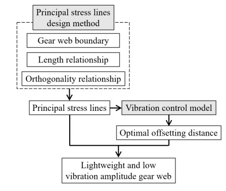
A lightweight and low vibration amplitude web design method was investigated to reduce gear weight and noise. It was based upon the relationship between length and orthogonality that the principal stress lines were designed at the gear web. By constructing a vibration control model with gear design parameters, the optimal distance was calculated. By offsetting the principal stress lines at the optimal distance, the lightweight gear web with the low vibration amplitude was then generated. A vibration experimental platform was built to verify the novel gear vibration performances, and it was compared with other gears with the same web's porosity to verify loading performance. The experimental results indicated that compared with the solid gear, the novel gear is 20.50% lighter and with a 29.46% vibration amplitude reduction.

| [1] | R. Ramadani, M. Kegl, J. Predan, A. Belšak, S. Pehan, Influence of cellular lattice body structure on gear vibration induced by meshing, J. Eng. Mech., 64 (2018), 611-620. |
| [2] | M. Faggioni, F. Samani, G. Bertacchi, F. Pellicano, Dynamic optimization of spur gears, Mech. Mach. Theory, 46 (2011), 544-557. |
| [3] | S. Li, Experimental investigation and FEM analysis of resonance frequency behavior of three-dimensional, thin-walled spur gears with a power-circulating test rig, Mech. Mach. Theory, 43 (2008), 934-963. |
| [4] | J. Smith, Gear noise and vibration, Marcel Dekker, (2003), 1-12. |
| [5] | S. Ghosh, G. Chakraborty, On optimal tooth profile modification for reduction of vibration and noise in spur gear pairs, Mech. Mach. Theory, 105 (2016), 145-163. |
| [6] | R. Handschuh, G. Roberts, R. Sinnamon, B. Stringer, D. Dykas, W. Kohlman, et al., Hybrid gear preliminary results-application of composites to dynamic mechanical components, Nasa Tm., (2012), 217630. |
| [7] | W. Xiao, Y. Huang, H. Jiang, J. Lina, Effect of powder material on vibration reduction of gear system in centrifugal field, Adv. Powder. Technol., 294 (2016), 146-158. |
| [8] | R. Ramadani, A. Belsak, M. Kegl, J. Predan, S. Pehan, Topology optimization based design of lightweight and low vibration gear bodies, Int. J. Simul. Model., 17 (2018), 92-104. |
| [9] | D. Li, W. Liao, N. Dai, G. Dong, Y. Tang, Y. Xie, Optimal design and modeling of gyroid-based functionally graded cellular structures for additive manufacturing, Comput. Aided. Design., 104 (2018), 87-99. |
| [10] | J. Zhou, J. Su, Ansys workbench detailed analysis of finite element examples (dynamics), Posts & Telecom Press, (2019), 81-110. |
| [11] | N. Aage, E. Andreassen, B. Lazarov, O. Sigmund, Giga-voxel computational morphogenesis for structural design, Nature, 550 (2017), 84-86. |
| [12] | J. Zhang, B. Wang, F. Niu, G. Cheng, Design optimization of connection section for concentrated force diffusion, Mech. Based. Des. Struc., 43 (2015), 209-231. |
| [13] | D. Gao, On Topology optimization and canonical duality method, Comput. Method. Appl. M., 341 (2018), 249-277. |
| [14] | T. Kwok, Y. Li, Y. Chen, A structural topology design method based on principal stress line, Comput. Aided. Design., 80 (2016), 19-31. |
| [15] | G. Xu, N. Dai, Michell truss design for lightweight gear bodies, Math. Biosci. Eng., 18 (2021), 1653-1669. |
| [16] | R. E. Skelton, M. C. de Oliveira, Optimal tensegrity structures in bending: the discrete Michell truss, J. Franklin. Inst., 347 (2010), 257-283. |
| [17] | A. Mazurek, W. Baker, C. Tork, Geometrical aspects of optimum truss like structures, Struct. Multidiscip. Optim., 43 (2010), 231-242. |


Figures(15) / Tables(4)

Ganjun Xu, Ning Dai, Sukun Tian. Principal stress lines based design method of lightweight and low vibration amplitude gear web[J]. Mathematical Biosciences and Engineering, 2021, 18(6): 7060-7075. doi: 10.3934/mbe.2021351


 DownLoad: