This paper focuses on the investigation of the flexural behaviour of steel-concrete composite beams through non-linear finite element analysis. Both geometries, as well as material non-linearity, are considered. Steel-concrete composite beams are typically made consisting of a hot-rolled I-section steel beam and a concrete slab that is connected monolithically by using a shear connector. A shear connector is one of the key elements for developing the composite action used in steel-concrete composite structures. This paper deals with the flexible shear connectors such as studs and channels designed as per the Indian standards 11384. Initially, the FE models are validated by making comparisons with the experimental test results obtained by previous researchers, as available in the literature. In the present study, thirty three-dimensional simply supported composite beams are created and analysed using finite element commercial software package ANSYS15 workbench version subjected to two-point loads. The degree of shear connection, the strength of steel section and the geometry of stud and channel connectors are the primary parameters considered for the present research work, and the results are compared. The overall flexural response is provided, including failure modes, load-central deformation behaviour, and interface slip, as well as the effects of yield strength of steel, the geometry of the stud and channel shear connector along with the degree of shear interaction, are evaluated. The results show that the degree of interaction, the geometry of shear connectors and steel yield strength have significant influence. Subjected to flexure, steel-concrete composite beam section with channel connector is less evaluated so far; therefore, in the present research work, channel shear connector is taken into account to evaluate the flexural behaviour with the consideration of varying grades of steel section along with the degree of interaction and to compare the results with a different section of shear connectors.
Citation: Sougata Chattopadhyay, Umamaheswari N. Numerical investigation of steel-concrete composite beams using flexible shear connectors[J]. AIMS Materials Science, 2022, 9(5): 668-683. doi: 10.3934/matersci.2022041
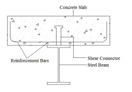
This paper focuses on the investigation of the flexural behaviour of steel-concrete composite beams through non-linear finite element analysis. Both geometries, as well as material non-linearity, are considered. Steel-concrete composite beams are typically made consisting of a hot-rolled I-section steel beam and a concrete slab that is connected monolithically by using a shear connector. A shear connector is one of the key elements for developing the composite action used in steel-concrete composite structures. This paper deals with the flexible shear connectors such as studs and channels designed as per the Indian standards 11384. Initially, the FE models are validated by making comparisons with the experimental test results obtained by previous researchers, as available in the literature. In the present study, thirty three-dimensional simply supported composite beams are created and analysed using finite element commercial software package ANSYS15 workbench version subjected to two-point loads. The degree of shear connection, the strength of steel section and the geometry of stud and channel connectors are the primary parameters considered for the present research work, and the results are compared. The overall flexural response is provided, including failure modes, load-central deformation behaviour, and interface slip, as well as the effects of yield strength of steel, the geometry of the stud and channel shear connector along with the degree of shear interaction, are evaluated. The results show that the degree of interaction, the geometry of shear connectors and steel yield strength have significant influence. Subjected to flexure, steel-concrete composite beam section with channel connector is less evaluated so far; therefore, in the present research work, channel shear connector is taken into account to evaluate the flexural behaviour with the consideration of varying grades of steel section along with the degree of interaction and to compare the results with a different section of shear connectors.

| [1] |
Liang QQ, Brian U, Mark AB, et al. (2005) Strength analysis of steel-concrete composite beams in combined bending and shear. J Struct Eng 131: 1593–1600. https://doi.org/10.1061/(ASCE)0733-9445(2005)131:10(1593) doi: 10.1061/(ASCE)0733-9445(2005)131:10(1593)

|
| [2] |
Shervin M, Saman B (2008) Behavior of channel shear connectors Part I: experimental study. J Constr Steel Res 64: 1333–1340. https://doi.org/10.1016/j.jcsr.2008.01.010 doi: 10.1016/j.jcsr.2008.01.010
|
| [3] |
Queiroza FD, Vellascob PCGS, Nethercot DA (2007) Finite element modelling of composite beams with full and partial shear connection. J Constr Steel Res 63: 505–521. https://doi.org/10.1016/j.jcsr.2006.06.003 doi: 10.1016/j.jcsr.2006.06.003
|
| [4] |
Madhusudan GK, Akhil U (2020) Numerical study on the deformation behavior of steel concrete composite girders considering partial shear interaction. Structures 23: 437–446. https://doi.org/10.1016/j.istruc.2019.10.007 doi: 10.1016/j.istruc.2019.10.007
|
| [5] |
Amar P, Monika AP, Anandavalli N (2021) Behaviour of steel-concrete composite (SCC) girder under impact due to rock fall. J Constr Steel Res 177: 106474. https://doi.org/10.1016/j.jcsr.2020.106474 doi: 10.1016/j.jcsr.2020.106474
|
| [6] | Bureau of Indian Standards (1986) Code of practice for composite construction in structural steel and concrete. IS 11384. |
| [7] | European Committee for standardization (2004) Eurocode 4: Design of composite steel and concrete structures-Part 1-1: General rules and rules for buildings. EN 1994-1-1. |
| [8] | Chapman JC, Balakrishnan S (1964) Experiments on composite beams. J Struct Eng 42: 369–383. |
| [9] |
Liu X, Bradford MA, Ataei A (2017) Flexural performance of innovative sustainable composite steel-concrete beams. Eng Struct 130: 282–296. https://doi.org/10.1016/j.engstruct.2016.10.009 doi: 10.1016/j.engstruct.2016.10.009
|
| [10] |
Ban H, Bradford MA (2013) Flexural behaviour of composite beams with high strength steel. Eng Struct 56: 1130–1141. https://doi.org/10.1016/j.engstruct.2013.06.040 doi: 10.1016/j.engstruct.2013.06.040
|


Figures(12) / Tables(5)

Sougata Chattopadhyay, Umamaheswari N. Numerical investigation of steel-concrete composite beams using flexible shear connectors[J]. AIMS Materials Science, 2022, 9(5): 668-683. doi: 10.3934/matersci.2022041


 DownLoad: