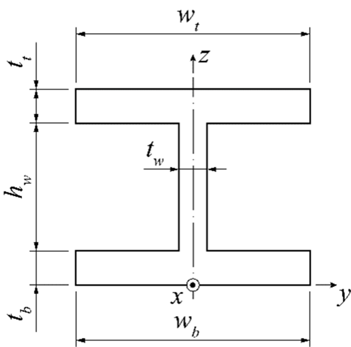
Functionally graded materials are well-known for their ability to minimize abrupt stress transitions that are typical of laminated composites, as well as for being very suitable to operate in adverse high-temperature environments. They can act as thermal barriers if a proper selection of the constituent materials is considered. These materials and structures have attracted the attention of many researchers; however, previous research efforts have been focused on the systematic study of rectangular-shaped cross-section profiles. The use of beams characterized by other cross-sections, which are commonly used in metallic construction, may benefit from the continuous, smooth materials mixture that is typically found within functionally graded composites. Hence, this work aims to investigate the behavior of symmetrical, I-shaped, cross-section beams made from these advanced composites by performing a set of parametric analyses. These beams are modeled after solid finite elements to be able to describe the materials mixture evolution through the beam thickness with greater detail. Thick and moderately thick beams are submitted to static loading while considering different boundary conditions, and their linear static behavior is analyzed. As expected, the stress profiles are highly influenced by the materials' mixture profiles. Significant shear stress was found in the I-shaped cross sections.
Citation: M.A.R. Loja, André Carvalho, Ines C.J. Barbosa. A study on the static behavior of functionally graded I-shaped beams[J]. AIMS Materials Science, 2024, 11(1): 28-57. doi: 10.3934/matersci.2024002
Functionally graded materials are well-known for their ability to minimize abrupt stress transitions that are typical of laminated composites, as well as for being very suitable to operate in adverse high-temperature environments. They can act as thermal barriers if a proper selection of the constituent materials is considered. These materials and structures have attracted the attention of many researchers; however, previous research efforts have been focused on the systematic study of rectangular-shaped cross-section profiles. The use of beams characterized by other cross-sections, which are commonly used in metallic construction, may benefit from the continuous, smooth materials mixture that is typically found within functionally graded composites. Hence, this work aims to investigate the behavior of symmetrical, I-shaped, cross-section beams made from these advanced composites by performing a set of parametric analyses. These beams are modeled after solid finite elements to be able to describe the materials mixture evolution through the beam thickness with greater detail. Thick and moderately thick beams are submitted to static loading while considering different boundary conditions, and their linear static behavior is analyzed. As expected, the stress profiles are highly influenced by the materials' mixture profiles. Significant shear stress was found in the I-shaped cross sections.

| [1] |
Koizumi M (1997) FGM activities in Japan. Compos B Eng 28: 1–4. https://doi.org/10.1016/S1359-8368(96)00016-9 doi: 10.1016/S1359-8368(96)00016-9

|
| [2] |
Sayyad AS, Ghugal YM (2019) Modeling and analysis of functionally graded sandwich beams: a review. Mech Adv Mater Struct 26: 1776–1795. https://doi.org/10.1080/15376494.2018.1447178 doi: 10.1080/15376494.2018.1447178
|
| [3] |
Saleh B, Jiang J, Fathi R, et al. (2020) 30 years of functionally graded materials: An overview of manufacturing methods, applications and future challenges. Compos B Eng 201: 108376. https://doi.org/10.1016/j.compositesb.2020.108376 doi: 10.1016/j.compositesb.2020.108376
|
| [4] |
Garg A, Belarbi MO, Chalak H, et al. (2021) A review of the analysis of sandwich fgm structures. Compos Struct 258: 113427. https://doi.org/10.1016/j.compstruct.2020.113427 doi: 10.1016/j.compstruct.2020.113427
|
| [5] |
Parihar RS, Setti SG, Sahu RK (2018) Recent advances in the manufacturing processes of functionally graded materials: A review. IEEE J Sel Top Quantum Electron 25: 309–336. https://doi.org/10.1515/secm-2015-0395 doi: 10.1515/secm-2015-0395
|
| [6] |
Kanu NJ, Vates UK, Singh GK, et al. (2019) Fracture problems, vibration, buckling, and bending analyses of functionally graded materials: A state-of-the-art review including smart FGMS. Part Sci Technol 37: 583–608. https://doi.org/10.1080/02726351.2017.1410265 doi: 10.1080/02726351.2017.1410265
|
| [7] |
Banks-Sills L, Eliasi R, Berlin Y (2002) Modeling of functionally graded materials in dynamic analyses. Compos B Eng 33: 7–15. https://doi.org/10.1016/S1359-8368(01)00057-9 doi: 10.1016/S1359-8368(01)00057-9
|
| [8] | Kasem MM, Maalawi KY (2021) Multiobjective optimization of functionally graded material columns. 2021 3rd Novel Intelligent and Leading Emerging Sciences Conference (NILES) 323–326. https://doi.org/10.1109/NILES53778.2021.9600498 |
| [9] |
Dastjerdi FB, Jabbari M (2022) Analytical analysis for non-homogeneous two-layer functionally graded material. Nonlinear Eng 11: 598–608. https://doi.org/10.1515/nleng-2022-0258 doi: 10.1515/nleng-2022-0258
|
| [10] |
He D, Wang Q, Zhong R, et al. (2023) Vibration analysis of functionally graded material (FGM) double layered floating raft structure by the spectro-geometric method. Struct 48: 533–550. https://doi.org/10.1016/j.istruc.2022.11.111 doi: 10.1016/j.istruc.2022.11.111
|
| [11] |
Nguyen TT, Kim NI, Lee J (2016) Analysis of thin-walled open-section beams with functionally graded materials. Compos Struct 138: 75–83. https://doi.org/10.1016/j.compstruct.2015.11.052 doi: 10.1016/j.compstruct.2015.11.052
|
| [12] |
Loja MA, Barbosa JI (2020) In-plane functionally graded plates: A study on the free vibration and dynamic instability behaviours. Compos Struct 237: 4. https://doi.org/10.1016/j.compstruct.2020.111905 doi: 10.1016/j.compstruct.2020.111905
|
| [13] |
Asiri S (2022) Comparative modal analysis on fishing rod made of functionally graded composite material using finite element analysis. J Appl Biomater Funct Mater 20: 3. https://doi.org/10.1177/22808000221089774 doi: 10.1177/22808000221089774
|
| [14] |
Filippi M, Carrera E, Zenkour AM (2015) Static analyses of FGM beams by various theories and finite elements. Compos B Eng 72: 1–9. doi: 10.1016/j.compositesb.2014.12.004 doi: 10.1016/j.compositesb.2014.12.004
|
| [15] |
Chakraborty A, Gopalakrishnan S, Reddy JN (2003) A new beam finite element for the analysis of functionally graded materials. Int J Mech Sci 45: 519–539. https://doi.org/10.1016/S0020-7403(03)00058-4 doi: 10.1016/S0020-7403(03)00058-4
|
| [16] |
Yoon K, Lee P. S, Kim DN (2015) Geometrically nonlinear finite element analysis of functionally graded 3D beams considering warping effects. Compos Struct 132: 1231–1247. https://doi.org/10.1016/j.compstruct.2015.07.024 doi: 10.1016/j.compstruct.2015.07.024
|
| [17] |
Costa DM, Loja MA (2017) Bat-inspired optimization of multilayered adaptive structures. Compos Struct 168: 189–215. https://doi.org/10.1016/j.compstruct.2017.01.067 doi: 10.1016/j.compstruct.2017.01.067
|
| [18] | Vallejos A, Ayala S, Arciniega R (2020) Improved first order formulation for buckling analysis of functionally graded beams. 2020 Congreso Internacional de Innovación y Tendencias en Ingeniería (CONⅡTI) 1–6. https://doi.org/10.1109/CONⅡTI51147.2020.9240368 |
| [19] |
Bian PL, Qing H, Yu T (2022) A new finite element method framework for axially functionally-graded nanobeam with stress-driven two-phase nonlocal integral model. Compos Struct 295: 9. https://doi.org/10.1016/j.compstruct.2022.115769 doi: 10.1016/j.compstruct.2022.115769
|
| [20] |
Mota AF, Loja MA, Barbosa JI, er al. (2022) Mechanical behavior of a sandwich plate with aluminum foam core, using an image-based layerwise model. Mech Adv Mater Struct 29: 4074–4095. https://doi.org/10.1080/15376494.2021.1919801 doi: 10.1080/15376494.2021.1919801
|
| [21] |
Luo Y (2023) Voxel-based design and characterization of functionally graded materials. Results Mater 17: 3. https://doi.org/10.1016/j.rinma.2023.100375 doi: 10.1016/j.rinma.2023.100375
|
| [22] | Luu NG, Banh TT (2023) Static, dynamic and stability analysis of multi-dimensional functional graded plate with variable thickness using deep neural network. Tech Rep https://doi.org/10.48550/arXiv.2301.05900 |
| [23] |
Penna R, Feo L, Lovisi G, et al. (2022) Application of the higher-order hamilton approach to the nonlinear free vibrations analysis of porous fg nano-beams in a hygrothermal environment based on a local/nonlocal stress gradient model of elasticity. Nanomater 12: 2098. https://doi.org/10.3390/nano12122098 doi: 10.3390/nano12122098
|
| [24] |
Penna R (2023) Bending analysis of functionally graded nanobeams based on stress-driven nonlocal model incorporating surface energy effects. Int J Eng Sci 189: 103887. https://doi.org/10.1016/j.ijengsci.2023.103887 doi: 10.1016/j.ijengsci.2023.103887
|
| [25] |
Lovisi G (2023) Application of the surface stress-driven nonlocal theory of elasticity for the study of the bending response of fg cracked nanobeams. Compos Struct 324: 117549. https://doi.org/10.1016/j.compstruct.2023.117549 doi: 10.1016/j.compstruct.2023.117549
|
| [26] |
Loja M, Rzeszut K, Barbosa J (2022) Nonlocal free vibrations of metallic fgm beams. J Compos Sci 6: 125. https://doi.org/10.3390/jcs6050125 doi: 10.3390/jcs6050125
|
| [27] |
Giunta G, Crisafulli D, Belouettar S, et al. (2013) A thermo-mechanical analysis of functionally graded beams via hierarchical modelling. Compos Struct 95: 676–690. https://doi.org/10.1016/j.compstruct.2012.08.013 doi: 10.1016/j.compstruct.2012.08.013
|
| [28] |
Qin Y, Li X, Yang E, et al. (2016) Flapwise free vibration characteristics of a rotating composite thin-walled beam under aerodynamic force and hygrothermal environment. Compos Struct 153: 490–503. https://doi.org/10.1016/j.compstruct.2016.06.057 doi: 10.1016/j.compstruct.2016.06.057
|
| [29] |
Valencia Murillo C, Gutierrez Rivera M, Celaya Garcia L (2023) Thermal–structural linear static analysis of functionally graded beams using reddy beam theory. Math Comput Appl 28: 84. https://doi.org/10.3390/mca28040084 doi: 10.3390/mca28040084
|
| [30] |
Tian J, Zhang Z, Hongxing H (2019) Free vibration analysis of rotating functionally graded double-tapered beam including porosities. Int J Mech Sci 150: 526–538. https://doi.org/10.1016/j.ijmecsci.2018.10.056 doi: 10.1016/j.ijmecsci.2018.10.056
|
| [31] |
Mota A, Loja M, Barbosa J, et al. (2020) Porous functionally graded plates: an assessment of shear correction factor influence on static behavior. Math Comput Appl 25: 25. https://doi.org/10.3390/mca25020025 doi: 10.3390/mca25020025
|
| [32] |
Akbas D, Fageehi Y, Assie A, et al. (2022) Dynamic analysis of viscoelastic functionally graded porous thick beams under pulse load. Eng Comput 38: 365–377. https://doi.org/10.1007/s00366-020-01070-3 doi: 10.1007/s00366-020-01070-3
|
| [33] |
Lee J, Lee B (2022) Coupled flexural-torsional free vibration of an axially functionally graded circular curved beam. Mech Compos Mater 57: 833–846. https://doi.org/10.1007/s11029-022-10003-8. doi: 10.1007/s11029-022-10003-8
|
| [34] |
Ö zmen U, Ö zhan B (2022) Computational modeling of functionally graded beams: A novel approach. J Vib Eng Technol 10: 2693–2701. https://doi.org/10.1007/s42417-022-00515-x doi: 10.1007/s42417-022-00515-x
|
| [35] |
Li Z, Xu Y, Huang D (2021) Analytical solution for vibration of functionally graded beams with variable cross-sections resting on pasternak elastic foundations. Int J Mech Sci 191: 106084. https://doi.org/10.1016/j.ijmecsci.2020.106084 doi: 10.1016/j.ijmecsci.2020.106084
|
| [36] |
Gaspar J, Loja M, Barbosa J (2023) Static and free vibration analyses of functionally graded plane structures. J compos sci 7: 377. https://doi.org/10.3390/jcs7090377 doi: 10.3390/jcs7090377
|
| [37] |
Loja MR, Barbosa J, Soares CM (1997) Buckling behaviour of laminated beam structures using a higher order discrete model. Compos Struct 38: 119–131. https://doi.org/10.1016/S0263-8223(98)80011-1 doi: 10.1016/S0263-8223(98)80011-1
|
| [38] |
Carvalho A, Silva T, Loja M, et al. (2017) Assessing the influence of material and geometrical uncertainty on the mechanical behavior of functionally graded material plates. Mech Adv Mater Struct 24: 417–426. https://doi.org/10.1080/15376494.2016.1191100 doi: 10.1080/15376494.2016.1191100
|
| [39] | Reddy JN (2003) Mechanics of Laminated Composite Plates and Shells, 2 Eds., CRC Press, Boca Raton. |
| [40] |
Carvalho A (2023) Study of damping of bare and encased steel I-Beams using the thermoelastic model. Buildings 13: 2964. https://doi.org/10.3390/buildings13122964 doi: 10.3390/buildings13122964
|
| [41] | Dassault Systèmes (2021) Solidworks. Available from: https://www.solidworks.com/. |
| [42] | Martha L (2018) Ftool-two-dimensional frame analysis tool. Available from: https://www.ftool.com.br/Ftool/. |


Figures(13) / Tables(11)

M.A.R. Loja, André Carvalho, Ines C.J. Barbosa. A study on the static behavior of functionally graded I-shaped beams[J]. AIMS Materials Science, 2024, 11(1): 28-57. doi: 10.3934/matersci.2024002


 DownLoad: