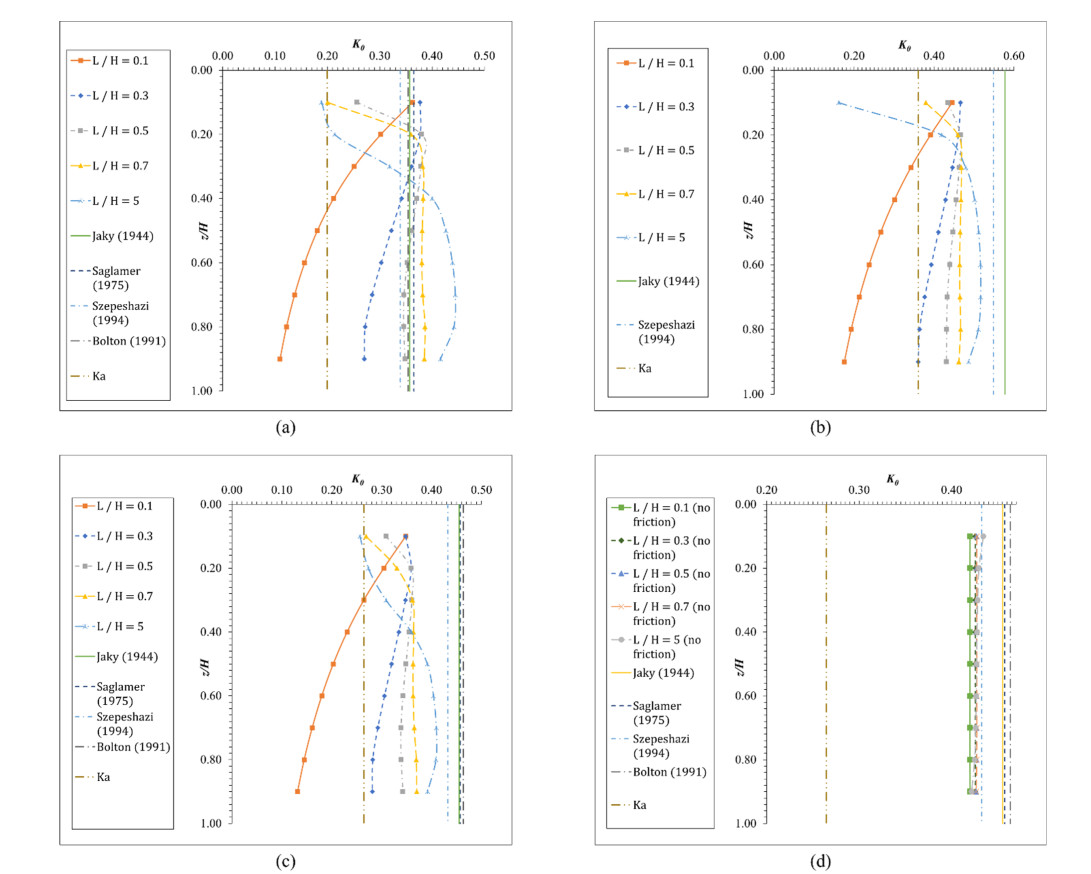
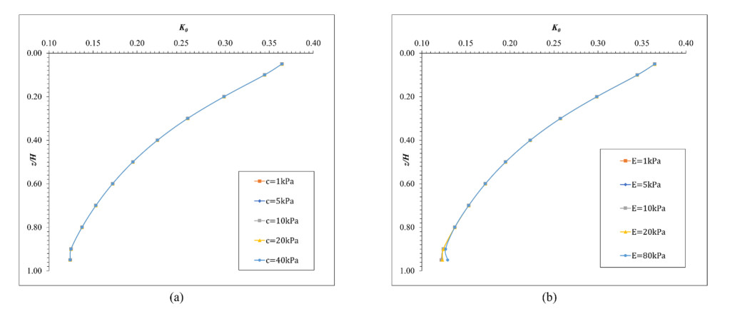
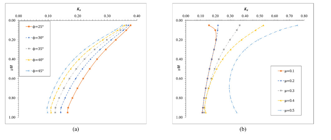
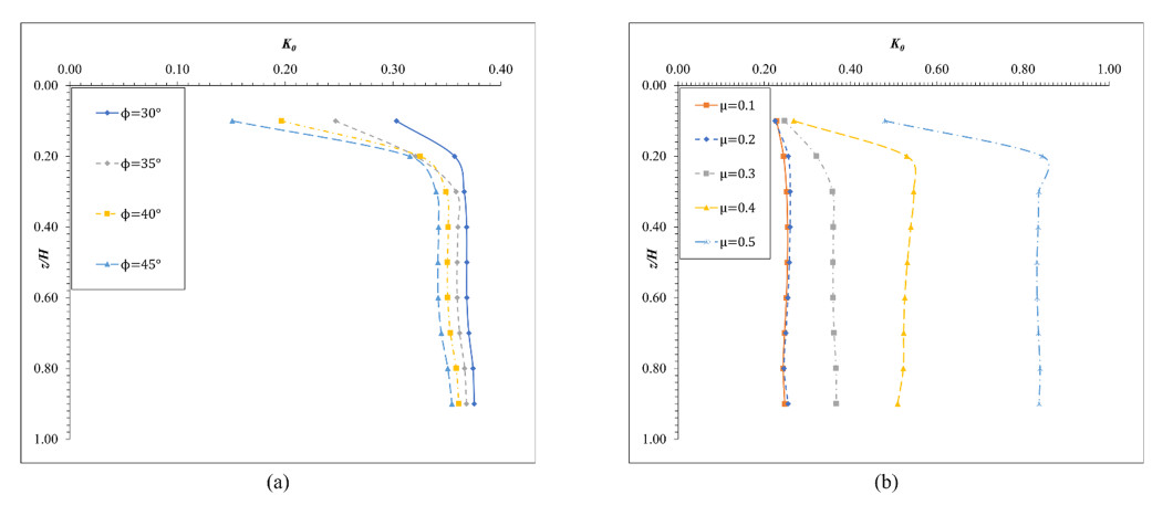
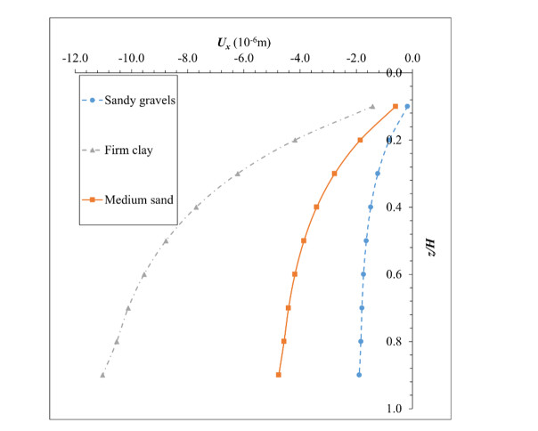
The lateral earth pressure at rest is typically considered in situations where lateral wall movements are negligible. Determining the coefficient of lateral earth pressure at rest (referred to as K0) often relies on established classical equations. However, these equations often overlook the influence of the width of the backfill soil on lateral earth pressure. While this omission is generally acceptable when the backfill soil is wide enough, there are instances where a retaining wall supports backfill soils of limited width, such as basement walls between adjacent buildings. Yet, there is limited research addressing the impact of narrow backfill in such scenarios. We aimed to address this gap by investigating variations in K0 values under different conditions, including backfill width and soil properties. Using ABAQUS for numerical simulations, we refined and validated our model using relevant laboratory experimental data. Subsequently, the validated model was applied to various simulation scenarios. For narrow backfill widths (ranging from 0.1 to 0.7 times the retaining wall height), our findings indicated a general decrease in K0 values with decreasing backfill widths, often smaller than those estimated using classical equations. Additionally, along the depth of the wall, K0 values tended to decrease with increasing depth for narrow backfill widths. These findings contribute to our understanding of the impact of narrow backfill on K0.
Citation: Ningxin Weng, Lei Fan, Cheng Zhang, Guobin Gong, Lihua Tan. At-rest lateral earth pressure coefficient under narrow backfill widths: A numerical investigation[J]. AIMS Geosciences, 2024, 10(2): 274-289. doi: 10.3934/geosci.2024016
The lateral earth pressure at rest is typically considered in situations where lateral wall movements are negligible. Determining the coefficient of lateral earth pressure at rest (referred to as K0) often relies on established classical equations. However, these equations often overlook the influence of the width of the backfill soil on lateral earth pressure. While this omission is generally acceptable when the backfill soil is wide enough, there are instances where a retaining wall supports backfill soils of limited width, such as basement walls between adjacent buildings. Yet, there is limited research addressing the impact of narrow backfill in such scenarios. We aimed to address this gap by investigating variations in K0 values under different conditions, including backfill width and soil properties. Using ABAQUS for numerical simulations, we refined and validated our model using relevant laboratory experimental data. Subsequently, the validated model was applied to various simulation scenarios. For narrow backfill widths (ranging from 0.1 to 0.7 times the retaining wall height), our findings indicated a general decrease in K0 values with decreasing backfill widths, often smaller than those estimated using classical equations. Additionally, along the depth of the wall, K0 values tended to decrease with increasing depth for narrow backfill widths. These findings contribute to our understanding of the impact of narrow backfill on K0.

| [1] |
Bathurst R, Cai Z (1995) Pseudo-static seismic analysis of geosynthetic-reinforced segmental retaining walls. Geosynth Int 2: 787–830. https://doi.org/10.1680/gein.2.0037 doi: 10.1680/gein.2.0037

|
| [2] |
Leshchinsky D, Leshchinsky B, Leshchinsky O (2017) Limit state design framework for geosynthetic-reinforced soil structures. Geotextiles Geomembranes 45: 642–652. https://doi.org/10.1016/j.geotexmem.2017.08.005 doi: 10.1016/j.geotexmem.2017.08.005
|
| [3] |
Pain A, Choudhury D, Bhattacharyya S (2017) Effect of dynamic soil properties and frequency content of harmonic excitation on the internal stability of reinforced soil retaining structure. Geotextiles Geomembranes 45: 471–486. https://doi.org/10.1016/j.geotexmem.2017.07.003 doi: 10.1016/j.geotexmem.2017.07.003
|
| [4] |
Steedman R, Zeng X (1990) The influence of phase on the calculation of pseudo-static earth pressure on a retaining wall. Geotechnique 40: 103–112. https://doi.org/10.1680/geot.1990.40.1.103 doi: 10.1680/geot.1990.40.1.103
|
| [5] |
Huang J, Parsons RL, Han J, et al. (2011) Numerical analysis of a laterally loaded shaft constructed within an MSE wall. Geotextiles Geomembranes 29: 233–241. https://doi.org/10.1016/j.geotexmem.2010.11.003 doi: 10.1016/j.geotexmem.2010.11.003
|
| [6] |
Bathurst R, Hatami K (1998) Seismic response analysis of a geosynthetic-reinforced soil retaining wall. Geosynth Int 5: 127–166. https://doi.org/10.1680/gein.5.0117 doi: 10.1680/gein.5.0117
|
| [7] |
Zheng Y, Fox PJ, McCartney JS (2018) Numerical simulation of deformation and failure behavior of geosynthetic reinforced soil bridge abutments. J Geotech Geoenviron 144: 04018037. https://doi.org/10.1061/(ASCE)GT.1943-5606.0001893 doi: 10.1061/(ASCE)GT.1943-5606.0001893
|
| [8] |
Garcia‐Suarez J, Asimaki D (2020) Exact seismic response of smooth rigid retaining walls resting on stiff soil. Int J Numer Anal Met 44: 1750–1769. https://doi.org/10.1002/nag.3082 doi: 10.1002/nag.3082
|
| [9] |
Mojallal M, Ghanbari A, Askari F (2012) A new analytical method for calculating seismic displacements in reinforced retaining walls. Geosynth Int 19: 212–231. https://doi.org/10.1680/gein.2012.12.00010 doi: 10.1680/gein.2012.12.00010
|
| [10] |
Xie Y, Leshchinsky B, Yang S (2016) Evaluating reinforcement loading within surcharged segmental block reinforced soil walls using a limit state framework. Geotextiles Geomembranes 44: 832–844. https://doi.org/10.1016/j.geotexmem.2016.06.010 doi: 10.1016/j.geotexmem.2016.06.010
|
| [11] |
Leshchinsky D, Kang B, Han J, et al. (2014) Framework for limit state design of geosynthetic-reinforced walls and slopes. Transp Infrastruct Geotechnol 1: 129–164. https://doi.org/10.1007/s40515-014-0006-3 doi: 10.1007/s40515-014-0006-3
|
| [12] |
Mylonakis G, Kloukinas P, Papantonopoulos C (2007) An alternative to the Mononobe–Okabe equations for seismic earth pressures. Soil Dyn Earthq Eng 27: 957–969. https://doi.org/10.1016/j.soildyn.2007.01.004 doi: 10.1016/j.soildyn.2007.01.004
|
| [13] |
Choudhury D, Nimbalkar S (2007) Seismic rotational displacement of gravity walls by pseudo-dynamic method: Passive case. Soil Dyn Earthq Eng 27: 242–249. https://doi.org/10.1016/j.soildyn.2006.06.009 doi: 10.1016/j.soildyn.2006.06.009
|
| [14] |
Choudhury D, Nimbalkar S (2005) Seismic passive resistance by pseudo-dynamic method. Geotechnique 55: 699–702. https://doi.org/10.1680/geot.2005.55.9.699 doi: 10.1680/geot.2005.55.9.699
|
| [15] |
Nimbalkar S, Choudhury D (2007) Sliding stability and seismic design of retaining wall by pseudo-dynamic method for passive case. Soil Dyn Earthq Eng 27: 497–505. https://doi.org/10.1016/j.soildyn.2006.11.006 doi: 10.1016/j.soildyn.2006.11.006
|
| [16] |
Choudhury D, Nimbalkar SS (2006) Pseudo-dynamic approach of seismic active earth pressure behind retaining wall. Geotech Geol Eng 24: 1103–1113. https://doi.org/10.1007/s10706-005-1134-x doi: 10.1007/s10706-005-1134-x
|
| [17] |
Eskandarinejad A, Shafiee A (2011) Pseudo-dynamic analysis of seismic stability of reinforced slopes considering non-associated flow rule. J Cent South Univ T 18: 2091–2099. https://doi.org/10.1007/s11771-011-0948-3 doi: 10.1007/s11771-011-0948-3
|
| [18] | Jaky J (1944) The coefficient of earth pressure at rest. J Soc Hung Archit Eng. |
| [19] | Saglamer A (1975) Soil parameters affecting coefficient of earth pressure at rest of cohesionless soils. In Proceedings of Istanbul conference on soil/mechanics and Foundation Engineering, Istanbul, Turkey, 9–16. |
| [20] | Bolton MD (2013) A guide to soil mechanics: Universities Press. https://doi.org/10.1007/978-1-349-16208-6 |
| [21] | Szepeshazi R (1994) ON THE K₀ FACTOR. Period Polytech Civ Eng 38: 127–135. |
| [22] |
Schö pfer MP, Abe S, Childs C, et al. (2009) The impact of porosity and crack density on the elasticity, strength and friction of cohesive granular materials: Insights from DEM modelling. Int J Rock Mech Min Sci 46: 250–261. https://doi.org/10.1016/j.ijrmms.2008.03.009 doi: 10.1016/j.ijrmms.2008.03.009
|
| [23] |
Rad AB (2018) Static analysis of non-uniform 2D functionally graded auxetic-porous circular plates interacting with the gradient elastic foundations involving friction force. Aerosp Sci Technol 76: 315–339. https://doi.org/10.1016/j.ast.2018.01.036 doi: 10.1016/j.ast.2018.01.036
|
| [24] |
Cornforth DH (1964) Some experiments on the influence of strain conditions on the strength of sand. Geotechnique 14: 143–167. https://doi.org/10.1680/geot.1964.14.2.143 doi: 10.1680/geot.1964.14.2.143
|
| [25] |
Mesri G, Hayat T (1993) The coefficient of earth pressure at rest. Can Geotech J 30: 647–666. https://doi.org/10.1139/t93-056 doi: 10.1139/t93-056
|
| [26] |
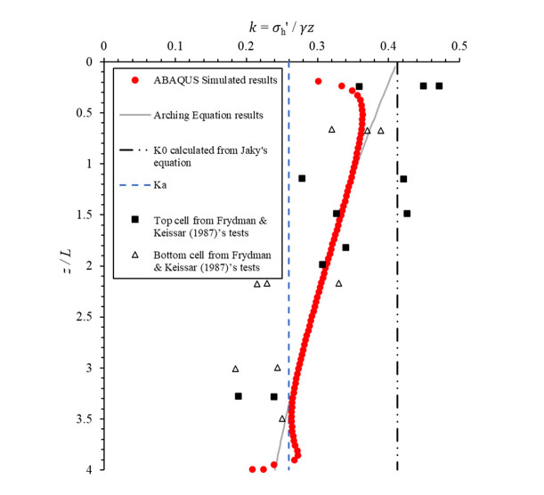
Frydman S, Keissar I (1987) Earth pressure on retaining walls near rock faces. J Geotech Eng 113: 586–599. https://doi.org/10.1061/(ASCE)0733-9410(1987)113:6(586) doi: 10.1061/(ASCE)0733-9410(1987)113:6(586)
|
| [27] |
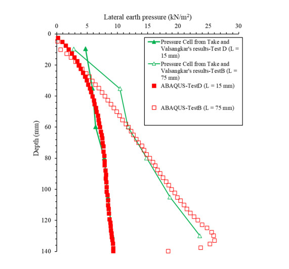
Take W, Valsangkar A (2001) Earth pressures on unyielding retaining walls of narrow backfill width. Can Geotech J 38: 1220–1230. https://doi.org/10.1139/t01-063 doi: 10.1139/t01-063
|
| [28] | Kniss KT, Yang KH, Wright SG, et al. (2007) Earth pressures and design considerations of narrow MSE walls. Proc Texas Section ASCE Spring 2007. Available from: https://sites.utexas.edu/zornberg/files/2022/03/Kniss_Yang_Wright_Zornberg_2007.pdf. |
| [29] |
Handy RL (1985) The arch in soil arching. J Geotech Eng 111: 302–318. https://doi.org/10.1061/(ASCE)0733-9410(1985)111:3(302) doi: 10.1061/(ASCE)0733-9410(1985)111:3(302)
|
| [30] |
Aggour M, Brown C (1974) The prediction of earth pressure on retaining walls due to compaction. Geotechnique 24: 489–502. https://doi.org/10.1680/geot.1974.24.4.489 doi: 10.1680/geot.1974.24.4.489
|
| [31] | Janssen H (1895) Versuche uber getreidedruck in silozellen. Z ver deut Ing 39: 1045. |
| [32] | Woodruff R (2003) Centrifuge modeling for MSE-shoring composite walls: University of Colorado. |
| [33] |
Safardoost Siahmazgi A, Fathipour H, Jamshidi Chenari R, et al. (2022) Evaluation of the pseudo-dynamic bearing capacity of surface footings on cohesionless soils using finite element lower bound limit analysis. Geomech Geoeng 17: 765–777. https://doi.org/10.1080/17486025.2021.1889686 doi: 10.1080/17486025.2021.1889686
|
| [34] |
Fathipour H, Tajani SB, Payan M, et al. (2022) Influence of transient flow during infiltration and isotropic/anisotropic matric suction on the passive/active lateral earth pressures of partially saturated soils. Eng Geol 310: 106883. https://doi.org/10.1016/j.enggeo.2022.106883 doi: 10.1016/j.enggeo.2022.106883
|
| [35] |
Fathipour H, Payan M, Jamshidi Chenari R, et al. (2021) Lower bound analysis of modified pseudo‐dynamic lateral earth pressures for retaining wall‐backfill system with depth‐varying damping using FEM‐Second order cone programming. Int J Numer Anal Met 45: 2371–2387. https://doi.org/10.1002/nag.3269 doi: 10.1002/nag.3269
|
| [36] |
Fathipour H, Siahmazgi AS, Payan M, et al. (2020) Evaluation of the lateral earth pressure in unsaturated soils with finite element limit analysis using second-order cone programming. Comput Geotech 125: 103587. https://doi.org/10.1016/j.compgeo.2020.103587 doi: 10.1016/j.compgeo.2020.103587
|
| [37] |
Fathipour H, Siahmazgi AS, Payan M, et al. (2021) Limit analysis of modified pseudodynamic lateral earth pressure in anisotropic frictional medium using finite-element and second-order cone programming. Int J Geomech 21: 04020258. https://doi.org/10.1061/(ASCE)GM.1943-5622.0001924 doi: 10.1061/(ASCE)GM.1943-5622.0001924
|
| [38] |
Mirmoazen SM, Lajevardi SH, Mirhosseini SM, et al. (2021) Active lateral earth pressure of geosynthetic-reinforced retaining walls with inherently anisotropic frictional backfills subjected to strip footing loading. Comput Geotech 137: 104302. https://doi.org/10.1016/j.compgeo.2021.104302 doi: 10.1016/j.compgeo.2021.104302
|
| [39] |
Fathipour H, Payan M, Chenari RJ (2021) Limit analysis of lateral earth pressure on geosynthetic-reinforced retaining structures using finite element and second-order cone programming. Comput Geotech 134: 104119. https://doi.org/10.1016/j.compgeo.2021.104119 doi: 10.1016/j.compgeo.2021.104119
|
| [40] | Yang KH, Liu CN (2007) Finite element analysis of earth pressures for narrow retaining walls. J Geoeng 2: 43–52. Available from: http://yo-1.ct.ntust.edu.tw/jge/files/articlefiles/v2i2200709051462998162.pdf. |
| [41] | Helwany S (2007) Applied soil mechanics with ABAQUS applications: John Wiley & Sons. https://doi.org/10.1002/9780470168097 |
| [42] | Li L, Aubertin M, Simon R, et al. (2003) Modeling arching effects in narrow backfilled stopes with FLAC. Flac and numerical modeling in geomechanics: 211–219. Available from: https://api.semanticscholar.org/CorpusID: 115066222 |
| [43] | Geotechdata (2023) Geotechnical Parameters. pp. Designed by Geotechdata.info. Developed by Nuevvo. Available from: https://www.geotechdata.info/. |
| [44] |
Motta E (1994) Generalized Coulomb active-earth pressure for distanced surcharge. J Geotech Eng 120: 1072–1079. https://doi.org/10.1061/(ASCE)0733-9410(1994)120:6(1072) doi: 10.1061/(ASCE)0733-9410(1994)120:6(1072)
|
| [45] |
Lade PV, Duncan JM (1975) Elastoplastic stress-strain theory for cohesionless soil. J Geotech Eng Divi 101: 1037–1053. https://doi.org/10.1061/AJGEB6.0000204 doi: 10.1061/AJGEB6.0000204
|
| [46] |
Kodicherla SPK, Gong G, Fan L, et al. (2018) Effects of preparation methods on inherent fabric anisotropy and packing density of reconstituted sand. Cogent Eng 5: 1533363. https://doi.org/10.1080/23311916.2018.1533363 doi: 10.1080/23311916.2018.1533363
|
| [47] |
Kodicherla SPK, Gong G, Yang Z, et al. (2019) The influence of particle elongations on direct shear behaviour of granular materials using DEM. Granular Matter 21: 86. https://doi.org/10.1007/s10035-019-0947-x doi: 10.1007/s10035-019-0947-x
|
| [48] |
Kodicherla SPK, Gong G, Fan L, et al. (2020) Investigations of the effects of particle morphology on granular material behaviors using a multi-sphere approach. J Rock Mech Geotech Eng 12: 1301–1312. https://doi.org/10.1016/j.jrmge.2020.04.005 doi: 10.1016/j.jrmge.2020.04.005
|
| [49] | Das BM, Sobhan K (1990) Principles of geotechnical engineering. Available from: http://faculty.tafreshu.ac.ir/file/download/course/1583609876-principles-of-geotechnical-engineering-8th-das.pdf |
| [50] |
Goh AT (1993) Behavior of cantilever retaining walls. J Geotech Eng 119: 1751–1770. https://doi.org/10.1061/(ASCE)0733-9410(1993)119:11(1751) doi: 10.1061/(ASCE)0733-9410(1993)119:11(1751)
|
| [51] |
Harkness R, Powrie W, Zhang X, et al. (2000) Numerical modelling of full-scale tests on drystone masonry retaining walls. Géotechnique 50: 165-179. https://doi.org/10.1680/geot.2000.50.2.165 doi: 10.1680/geot.2000.50.2.165
|
| [52] |
Rowe RK, Skinner GD (2001) Numerical analysis of geosynthetic reinforced retaining wall constructed on a layered soil foundation. Geotextiles Geomembranes 19: 387–412. https://doi.org/10.1016/S0266-1144(01)00014-0 doi: 10.1016/S0266-1144(01)00014-0
|
| [53] |
Helwany S, Reardon G, Wu J (1999) Effects of backfill on the performance of GRS retaining walls. Geotextiles Geomembranes 17: 1–16. https://doi.org/10.1016/S0266-1144(98)00021-1 doi: 10.1016/S0266-1144(98)00021-1
|
| [54] |
Rao P, Chen Q, Zhou Y, et al. (2016) Determination of active earth pressure on rigid retaining wall considering arching effect in cohesive backfill soil. Int J Geomech 16: 04015082. https://doi.org/10.1061/(ASCE)GM.1943-5622.0000589 doi: 10.1061/(ASCE)GM.1943-5622.0000589
|
Figures(8) / Tables(3)

Ningxin Weng, Lei Fan, Cheng Zhang, Guobin Gong, Lihua Tan. At-rest lateral earth pressure coefficient under narrow backfill widths: A numerical investigation[J]. AIMS Geosciences, 2024, 10(2): 274-289. doi: 10.3934/geosci.2024016


 DownLoad: