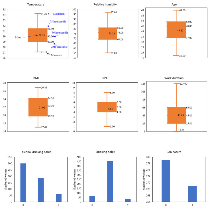
Worker assignment is a classic topic in infrastructure construction. In this study, we developed an integer optimization model to help decision-makers make optimal worker assignment plans while maximizing the daily productivity of all workers. Our proposed model considers the professional skills and physical fitness of workers. Using a real-world dataset, we adopted a machine learning method to estimate the maximum working tolerance time for different workers to carry out different jobs. The real-world dataset also demonstrates the effectiveness of our optimization model. Our work can help project managers achieve efficient management and save labor costs.
Citation: Haoqing Wang, Wen Yi, Yannick Liu. Optimal assignment of infrastructure construction workers[J]. Electronic Research Archive, 2022, 30(11): 4178-4190. doi: 10.3934/era.2022211
Worker assignment is a classic topic in infrastructure construction. In this study, we developed an integer optimization model to help decision-makers make optimal worker assignment plans while maximizing the daily productivity of all workers. Our proposed model considers the professional skills and physical fitness of workers. Using a real-world dataset, we adopted a machine learning method to estimate the maximum working tolerance time for different workers to carry out different jobs. The real-world dataset also demonstrates the effectiveness of our optimization model. Our work can help project managers achieve efficient management and save labor costs.

| [1] |
S. Wang, L. Zhen, D. Zhuge, Dynamic programming algorithms for selection of waste disposal ports in cruise shipping, Transp. Res. Part B Methodol., 108 (2018), 235–248. https://doi.org/10.1016/j.trb.2017.12.016 doi: 10.1016/j.trb.2017.12.016

|
| [2] |
S. Wang, D. Zhuge, L. Zhen, C. Y. Lee, Liner shipping service planning under sulfur emission regulations, Transp. Sci., 55 (2021), 491–509. https://doi.org/10.1287/trsc.2020.1010 doi: 10.1287/trsc.2020.1010
|
| [3] |
W. Sun, P. Bocchini, B. D. Davison, Resilience metrics and measurement methods for transportation infrastructure: the state of the art, Sustainable Resilient Infrastruct., 5 (2020), 168–199. https://doi.org/10.1080/23789689.2018.1448663 doi: 10.1080/23789689.2018.1448663
|
| [4] |
Y. Shen, C. Wang, Optimization of garbage bin layout in rural infrastructure for promoting the renovation of rural human settlements: case study of Yuding village in China, Int. J. Environ. Res. Public Health, 18 (2021), 11633. https://doi.org/10.3390/ijerph182111633 doi: 10.3390/ijerph182111633
|
| [5] |
J. Yuan, W. Yi, M. Miao, L. Zhang, Evaluating the impacts of health, social network and capital on craft efficiency and productivity: a case study of construction workers in China, Int. J. Environ. Res. Public Health, 15 (2018), 345. https://doi.org/10.3390/ijerph15020345 doi: 10.3390/ijerph15020345
|
| [6] |
M. Skibniewski, C. Hendrickson, Automation and robotics for road construction and maintenance, J. Transp. Eng., 116 (1990), 261–271. doi: 10.1061/(ASCE)0733-947X(1990)116:3(261)
|
| [7] |
Y. Lu, Y. Li, M. Skibniewski, Z. Wu, R. Wang, Y. Le, Information and communication technology applications in architecture, engineering, and construction oraanizations: a 15-year review, J. Manage. Eng., 31 (2015), 4014010. https://doi.org/10.1061/(ASCE)ME.1943-5479.0000319 doi: 10.1061/(ASCE)ME.1943-5479.0000319
|
| [8] |
C. Lu, C. Liu, Ecological control strategy for cooperative autonomous vehicle in mixed traffic considering linear stability, J. Intell. Connected Veh., 4 (2021), 115–124. https://doi.org/10.1108/JICV-08-2021-0012 doi: 10.1108/JICV-08-2021-0012
|
| [9] |
Q. Tian, Y. H. Lin, D. Z. W. Wang, Autonomous and conventional bus fleet optimization for fixed-route operations considering demand uncertainty, Transportation, 48 (2021), 2735–2763. https://doi.org/10.1007/s11116-020-10146-4 doi: 10.1007/s11116-020-10146-4
|
| [10] |
Q. Tian, Y. H. Lin. D. Z. W. Wang, Y. Liu, Planning for modular-vehicle transit service system: model formulation and solution methods, Transp. Res. Part C Emerging Technol., 138 (2022), 103627. https://doi.org/10.1016/j.trc.2022.103627 doi: 10.1016/j.trc.2022.103627
|
| [11] |
D. Huang, S. Wang, A two-stage stochastic programming model of coordinated electric bus charging scheduling for a hybrid charging scheme, Multimodal Transp., 1 (2022), 100006. https://doi.org/10.1016/j.multra.2022.100006 doi: 10.1016/j.multra.2022.100006
|
| [12] |
Q. Xu, K. Li, J. Wang, Q. Yuan, Y. Yang, W. Chu, The status, challenges, and trends: an interpretation of technology roadmap of intelligent and connected vehicles in China (2020), J. Intell. Connected Veh., 5 (2022), 1–7. https://doi.org/10.1108/JICV-07-2021-0010 doi: 10.1108/JICV-07-2021-0010
|
| [13] |
L. Yue, M. Abdel-Aty, Z. Wang, Effects of connected and autonomous vehicle merging behavior on mainline human-driven vehicle, J. Intell. Connected Veh., 5 (2022), 36–45. https://doi.org/10.1108/JICV-08-2021-0013 doi: 10.1108/JICV-08-2021-0013
|
| [14] |
H. Zhang, F. Liu, Y. Zhou, Z. Zhang, A hybrid method integrating an elite genetic algorithm with tabu search for the quadratic assignment problem, Inf. Sci., 539 (2020), 347–374. https://doi.org/10.1016/j.ins.2020.06.036 doi: 10.1016/j.ins.2020.06.036
|
| [15] |
H. Zhang, Q. Zhang, L. Ma, Z. Zhang, Y. Liu, A hybrid ant colony optimization algorithm for a multi-objective vehicle routing problem with flexible time windows, Inf. Sci., 490 (2019), 166–190. https://doi.org/10.1016/j.ins.2019.03.070 doi: 10.1016/j.ins.2019.03.070
|
| [16] |
Q. Su, D. Z. W. Wang, On the morning commute problem with distant parking options in the era of autonomous vehicles, Transp. Res. Part C Emerging Technol., 120 (2020), 102799. https://doi.org/10.1016/j.trc.2020.102799 doi: 10.1016/j.trc.2020.102799
|
| [17] |
A. P. Chan, W. Yi, D. W. Chan, D. P Wong, Using the thermal work limit as an environmental determinant of heat stress for construction workers, J. Manage. Eng., 29 (2013), 414–423. https://doi.org/10.1061/(ASCE)ME.1943-5479.0000162 doi: 10.1061/(ASCE)ME.1943-5479.0000162
|
| [18] |
R. Yan, S. Wang, J. Cao, D. Sun, Shipping domain knowledge informed prediction and optimization in port state control, Transp. Res. Part B Methodol., 149 (2021), 52–78. https://doi.org/10.1016/j.trb.2021.05.003 doi: 10.1016/j.trb.2021.05.003
|
| [19] |
Y. Zhang, A. D'Ariano, B. He, Q. Peng, Microscopic optimization model and algorithm for integrating train timetabling and track maintenance task scheduling, Transp. Res. Part B Methodol., 127 (2019), 237–278. https://doi.org/10.1016/j.trb.2019.07.010 doi: 10.1016/j.trb.2019.07.010
|
| [20] |
K. Wen, G. Zhao, B. He, J. Ma, H. Zhang, A decomposition-based forecasting method with transfer learning for railway short-term passenger flow in holidays, Expert Syst. Appl., 189 (2022), 116102. https://doi.org/10.1016/j.eswa.2021.116102 doi: 10.1016/j.eswa.2021.116102
|
| [21] |
K. Chargui, T. Zouadi, A. E. Fallahi, M. Reghioui, T. Aouam, Coupling the ILS optimisation algorithm and a simulation process to solve the travelling quay-crane worker assignment and balancing problem, J. Oper. Res. Soc., 73 (2021), 1532–1548. https://doi.org/10.1080/01605682.2021.1907241 doi: 10.1080/01605682.2021.1907241
|
| [22] |
W. Yi, S. Wang, Multi-objective mathematical programming approach to construction laborer assignment with equity consideration, Comput.-Aided Civ. Infrastruct. Eng., 31 (2016), 954–965. https://doi.org/10.1111/mice.12239 doi: 10.1111/mice.12239
|
| [23] |
W. Yi, S. Wang, Mixed-integer linear programming on work-rest schedule design for construction sites in hot weather, Comput.-Aided Civ. Infrastruct. Eng., 32 (2017), 429–439. https://doi.org/10.1111/mice.12267 doi: 10.1111/mice.12267
|
| [24] |
M. Skibniewski, A. Armijos, Linear programming approach to construction equipment and labour assignments, Civil Eng. Syst., 7 (1990), 44–50. https://doi.org/10.1080/02630259008970569 doi: 10.1080/02630259008970569
|
| [25] |
M. Park, S. Ha, H. S. Lee, Y. K. Choi, H. Kim, S. Han, Lifting demand-based zoning for minimizing worker vertical transportation time in high-rise building construction, Autom. Constr., 32 (2013), 88–95. https://doi.org/10.1016/j.autcon.2013.01.010 doi: 10.1016/j.autcon.2013.01.010
|
| [26] |
K. L. Lim, J. Whitehead, D. Jia, Z. Zheng, State of data platforms for connected vehicles and infrastructures, Commun. Transp. Res., 1 (2021), 100013. https://doi.org/10.1016/j.commtr.2021.100013 doi: 10.1016/j.commtr.2021.100013
|
| [27] |
L. Zhu, F. R. Yu, Y. Wang, B. Ning, T. Tang, Big data analytics in intelligent transportation systems: a survey, IEEE Trans. Intell. Transp. Syst., 20 (2018), 383–398. https://doi.org/10.1109/TITS.2018.2815678 doi: 10.1109/TITS.2018.2815678
|
| [28] |
S. Wang, R. Yan, A global method from predictive to prescriptive analytics considering prediction error for "Predict, then optimize" with an example of low-carbon logistics, Cleaner Logist. Supply Chain, 4 (2022), 1–3. https://doi.org/10.1016/j.clscn.2022.100062 doi: 10.1016/j.clscn.2022.100062
|
| [29] |
R. Yan, S. Wang, Integrating prediction with optimization: models and applications in transportation management, Multimodal Transp., 1 (2022), 1–5. https://doi.org/10.1016/j.multra.2022.100018 doi: 10.1016/j.multra.2022.100018
|
| [30] |
Q. Cheng, S. Wang, Z. Liu, Y. Yuan, Surrogate-based simulation optimization approach for day-to-day dynamics model calibration with real data, Transp. Res. Part C Emerging Technol., 105 (2019), 422–438. https://doi.org/10.1016/j.trc.2019.06.009 doi: 10.1016/j.trc.2019.06.009
|
| [31] |
X. Qu, J. Zhang, S. Wang, On the stochastic fundamental diagram for freeway traffic: model development, analytical properties, validation, and extensive applications, Transp. Res. Part B Methodol., 104 (2017), 256–271. https://doi.org/10.1016/j.trb.2017.07.003 doi: 10.1016/j.trb.2017.07.003
|
| [32] |
S. Lee, L. M. Chang, M. Skibniewski, Automated recognition of surface defects using digital color image processing, Autom. Constr., 15 (2006), 540–549. https://doi.org/10.1016/j.autcon.2005.08.001 doi: 10.1016/j.autcon.2005.08.001
|
| [33] |
H. Avetisyan, M. Skibniewski, M. Mozaffarpour, Analyzing sustainability of construction equipment in the state of California, Front. Eng. Manage., 4 (2017), 138–145. https://doi.org/10.15302/J-FEM-2017013 doi: 10.15302/J-FEM-2017013
|
| [34] |
L. Zhen, Y. Hu, S. Wang, G. Laporte, Y. Wu, Fleet deployment and demand fulfillment for container shipping liners, Transp. Res. Part B Methodol., 120 (2019), 15–32. https://doi.org/10.1016/j.trb.2018.11.011 doi: 10.1016/j.trb.2018.11.011
|
| [35] |
S. Wang, X. Chen, X. Qu, Model on empirically calibrating stochastic traffic flow fundamental diagram, Commun. Transp. Res., 1 (2021), 100015. https://doi.org/10.1016/j.commtr.2021.100015 doi: 10.1016/j.commtr.2021.100015
|
| [36] |
W. Yi, A. P. C. Chan, Optimizing work-rest schedule for construction rebar workers in hot and humid environment, Build. Environ., 61 (2013), 104–113. https://doi.org/10.1016/j.buildenv.2012.12.012 doi: 10.1016/j.buildenv.2012.12.012
|
| [37] |
W. Yi, A. P. C. Chan, Optimal work pattern for construction workers in hot weather: a case study in Hong Kong, J. Comput. Civ. Eng., 29 (2014), 05014009. https://doi.org/10.1061/(ASCE)CP.1943-5487.0000419 doi: 10.1061/(ASCE)CP.1943-5487.0000419
|
| [38] |
A. P. C. Chan, W. Yi, D. P. Wong, M. C. Yam, D. W. Chan, Determining an optimal recovery time for construction rebar workers after working to exhaustion in a hot and humid environment, Build. Environ., 58 (2012), 163–171. https://doi.org/10.1016/j.buildenv.2012.07.006 doi: 10.1016/j.buildenv.2012.07.006
|
| [39] |
K. Wang, S. Wang, L. Zhen, X. Qu, Cruise service planning considering berth availability and decreasing marginal profit, Transp. Res. Part B Methodol., 95 (2017), 1–18. https://doi.org/10.1016/j.trb.2016.10.020 doi: 10.1016/j.trb.2016.10.020
|
| [40] |
L. Wang, X. Xue, Z. Zhao, Z. Wang, The impacts of transportation infrastructure on sustainable development: emerging trends and challenges, Int. J. Environ. Res. Public Health, 15 (2018), 1172. https://doi.org/10.3390/ijerph15061172 doi: 10.3390/ijerph15061172
|
| [41] |
L. Zhen, Y. Wu, S. Wang, G. Laporte, Green technology adoption for fleet deployment in a shipping network, Transp. Res. Part B Methodol., 139 (2020), 388–410. https://doi.org/10.1016/j.trb.2020.06.004 doi: 10.1016/j.trb.2020.06.004
|
| [42] |
H. Christensen, K. Søgaard, M. Pilegaard, H. B. Olsen, The importance of the work/rest pattern as a risk factor in repetitive monotonous work, Int. J. Ind. Ergon., 25 (2020), 367–373. https://doi.org/10.1016/S0169-8141(99)00025-6 doi: 10.1016/S0169-8141(99)00025-6
|
Figures(2) / Tables(5)
Haoqing Wang, Wen Yi, Yannick Liu. Optimal assignment of infrastructure construction workers[J]. Electronic Research Archive, 2022, 30(11): 4178-4190. doi: 10.3934/era.2022211


 DownLoad: