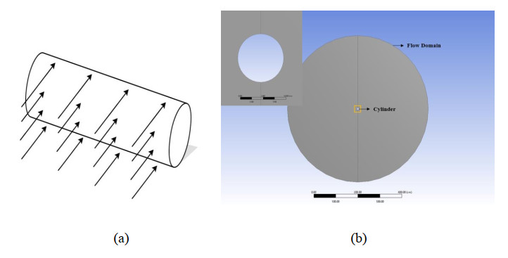
Researchers have extensively studied drag reduction because of its impact on a vehicle's fuel economy and structural stability, among other applications. A numerical study was carried out on the two-dimensional flow past a circular cylinder acting as a bluff body. In this case, the converging and diverging nozzles were used as passive flow control devices to reduce the drag coefficient. The subcritical Reynolds number 1×10⁵ was considered for the numerical study using ANSYS Fluent with the k-ω SST as a viscous model. Seven different outlet and inlet diameter ratios, Dout/Din, ranging from 0.2 to 1.4, were considered for the nozzle. The main focus of this research was to find the influence of a nozzle in a circular cylinder on decreasing drag. It was found that both the converging and diverging nozzles can be used in passive mode to reduce the drag coefficient. For the converging nozzle, a jet is formed at the exit of the nozzle, which produces thrust and ultimately reduces the drag coefficient. The flow rate increases through the nozzle with the increase in Dout/Din. This leads to a more extended jet, which fluctuates more because of the flow separation and the inherent nature of the vortex shedding of a circular cylinder. The drag coefficients are reduced by more than 30% in all the simulated cases. However, the drag reduction is more significant for the diverging nozzle and is greatly influenced by Dout/Din. Indeed, more than 38% of drag coefficients are reduced for Dout/Din = 1.4. On the other hand, the vortex shedding frequency is significantly higher for the diverging nozzle. Therefore, converging nozzles have an upper hand over the diverging nozzles. The grid independence test was achieved, and the numerical model was validated with results available in the open literature.
Citation: Sarker Ashraful Islam, Farhana Kabir Esheta, Md Mahir Shahriar, Dewan Hasan Ahmed. Numerical study of aerodynamic drag reduction of a circular cylinder with an inbuilt nozzle[J]. Metascience in Aerospace, 2024, 1(4): 379-400. doi: 10.3934/mina.2024018
Researchers have extensively studied drag reduction because of its impact on a vehicle's fuel economy and structural stability, among other applications. A numerical study was carried out on the two-dimensional flow past a circular cylinder acting as a bluff body. In this case, the converging and diverging nozzles were used as passive flow control devices to reduce the drag coefficient. The subcritical Reynolds number 1×10⁵ was considered for the numerical study using ANSYS Fluent with the k-ω SST as a viscous model. Seven different outlet and inlet diameter ratios, Dout/Din, ranging from 0.2 to 1.4, were considered for the nozzle. The main focus of this research was to find the influence of a nozzle in a circular cylinder on decreasing drag. It was found that both the converging and diverging nozzles can be used in passive mode to reduce the drag coefficient. For the converging nozzle, a jet is formed at the exit of the nozzle, which produces thrust and ultimately reduces the drag coefficient. The flow rate increases through the nozzle with the increase in Dout/Din. This leads to a more extended jet, which fluctuates more because of the flow separation and the inherent nature of the vortex shedding of a circular cylinder. The drag coefficients are reduced by more than 30% in all the simulated cases. However, the drag reduction is more significant for the diverging nozzle and is greatly influenced by Dout/Din. Indeed, more than 38% of drag coefficients are reduced for Dout/Din = 1.4. On the other hand, the vortex shedding frequency is significantly higher for the diverging nozzle. Therefore, converging nozzles have an upper hand over the diverging nozzles. The grid independence test was achieved, and the numerical model was validated with results available in the open literature.

| [1] | Eun LC, Rafie ASM, Wiriadidjaja S, et al. (2018) An overview of passive and active drag reduction methods for bluff body of road vehicles. Int J Eng Technol 7: 53–56. Available from: www.sciencepubco.com/index.php/IJET. |
| [2] |
Tsutsui T, Igarashi T (2002) Drag reduction of a circular cylinder in an air-stream. J Wind Eng Ind Aerod 90: 527–541. https://doi.org/10.1016/S0167-6105(01)00199-4 doi: 10.1016/S0167-6105(01)00199-4

|
| [3] |
Ahmed DH, Haque MA, Rauf M (2017) Investigation of Drag Coefficient at Subcritical and Critical Reynolds Number Region for Circular Cylinder with Helical Grooves. Int J Marit Technol 8: 25–33. https://doi.org/10.29252/ijmt.8.25 doi: 10.29252/ijmt.8.25
|
| [4] | Asif MA, Gupta AD, Rana MD, et al. (2016) Investigation of drag reduction through a flapping mechanism on circular cylinder, AIP Conference Proceedings. AIP Publishing, 1754. https://doi.org/10.1063/1.4958374 |
| [5] | Haidary FM, Mazumder A, Hasan MR, et al. (2020) Investigation for the drag reduction by introducing a passage through a circular cylinder. Ann Biomed Eng 1: 1–13. |
| [6] |
Boral A, Dutta S, Das A, et al. (2023) Drag Reduction for Flow Past Circular Cylinder Using Static Extended Trailing Edge. ASME Open J Eng 2. https://doi.org/10.1115/1.4057009 doi: 10.1115/1.4057009
|
| [7] |
Seo J, Yun J, Lee J (2023) Control of Turbulent Flow over a Circular Cylinder Using Tabs. Mathematics 11: 968. https://doi.org/10.3390/math11040968 doi: 10.3390/math11040968
|
| [8] |
Hasegawa M, Chen YC, Sakaue H (2022) Drag reduction study of a microfiber-coated cylinder. Sci Rep 12: 15022. https://doi.org/10.1038/s41598-022-19302-5 doi: 10.1038/s41598-022-19302-5
|
| [9] |
Bhuiyan SA, Hossain I, Redwan Hossain MSIMA, et al. (2024) Effect of a bioinspired upstream extended surface profile on flow characteristics and a drag coefficient of a circular cylinder. Metascience Aerosp 1: 130–158. https://doi.org/10.3934/mina.2024006 doi: 10.3934/mina.2024006
|
| [10] |
Bhuiyan SA, Hossain I, Redwan Hossain MSIMA, et al. (2024) Drag Reduction of A Finite Circular Cylinder with A Boxfish-Like Extended Surface. Acta Mech Malaysia 7: 28–39. https://doi.org/10.26480/amm.01.2024.28.39 doi: 10.26480/amm.01.2024.28.39
|
| [11] |
Sowoud KM, Al-Filfily AA, Abed BH (2020) Numerical Investigation of 2D Turbulent Flow past a Circular Cylinder at Lower Subcritical Reynolds Number. IOP Conf Ser Mater Sci Eng 881. https://doi.org/10.1088/1757-899X/881/1/012160 doi: 10.1088/1757-899X/881/1/012160
|
| [12] |
Mallick M, Kumar A, Murmu A (2015) Flow Modeling in Various Cylindrical Surfaces. Aquat Procedia 4: 834–840. https://doi.org/10.1016/j.aqpro.2015.02.104 doi: 10.1016/j.aqpro.2015.02.104
|
| [13] |
Catalano P, Wang M, Iaccarino G, et al. (2003) Numerical simulation of the flow around a circular cylinder at high Reynolds numbers. Int J Heat Fluid Flow 24: 463–469. https://doi.org/10.1016/S0142-727X(03)00061-4 doi: 10.1016/S0142-727X(03)00061-4
|
| [14] | Eppakayala N, Dileep KP, Kumar A (2017) Drag reduction over a circular cylinder. Int J Civ Eng Technol 8: 1334–1345. |
| [15] |
Shoshe M, Islam A, Ahmed DH (2021) Effect of an Upstream Extended Surface on Reduction of Total Drag for Finite Cylinders in Turbulent Flow. Int J Fluid Mech Res 48: 27–44. https://doi.org/10.1615/InterJFluidMechRes.2021038255 doi: 10.1615/InterJFluidMechRes.2021038255
|
| [16] |
Islam A, Shoshe MAMS, Ahmed DH (2023) Reduction of Total Drag for Finite Cylinders in Turbulent Flow with a Half-C Shape Upstream Body. Int J Fluid Mech Res 50: 41–53. https://doi.org/10.1615/InterJFluidMechRes.2022045488 doi: 10.1615/InterJFluidMechRes.2022045488
|
| [17] |
Zhang1a X, Li Z, Fu S (2014) Study of the flow around a cylinder from the subcritical to supercritical regimes. Ocean Syst Eng 4: 185–200. https://doi.org/10.12989/ose.2014.4.3.185 doi: 10.12989/ose.2014.4.3.185
|
| [18] |
Lausová L, Kološ I, Michalcová V (2019) Comparison of 2D Grid Simulations for Flow Past Cylinder at High Reynolds Numbers. Civil Environ Eng 15: 70–78. https://doi.org/10.2478/cee-2019-0010 doi: 10.2478/cee-2019-0010
|
| [19] | Zhang L, Wray T, Agarwal RK (2017) Numerical simulation of flow past a circular and a square cylinder at high reynolds number. 47th AIAA Fluid Dynamics Conferenc, 1–18. https://doi.org/10.2514/6.2017-3322 |
| [20] | Flores LA, Celis C, Blanco A (2019) Numerical and experimental characterization of subsonic flow around a circular cylinder: wind tunnel measurement capabilities and turbulence models suitability. https://doi.org/10.26678/abcm.encit2018.cit18-0195 |
| [21] |
Saidi N, Cerdoun M, Khalfallah S, et al. (2020) Numerical investigation of the surface roughness effects on the subsonic flow around a circular cone-cylinder. Aerosp Sci Technol 107: 106271. https://doi.org/10.1016/j.ast.2020.106271 doi: 10.1016/j.ast.2020.106271
|
| [22] |
Kološ I, Michalcová V, Lausová L (2021) Numerical analysis of flow around a cylinder in critical and subcritical regime. Sustainability (Switzerland) 13: 1–13. https://doi.org/10.3390/su13042048 doi: 10.3390/su13042048
|
| [23] |
Zaareer MNM, Mourad AHI, Darabseh T, et al. (2023) Impact of a vehicle exhaust pipe position on the lift and drag coefficients: 2D and 3D simulations. Int J Thermofluids 18. https://doi.org/10.1016/j.ijft.2023.100321 doi: 10.1016/j.ijft.2023.100321
|
| [24] | Conservation of Mass Equation | Ansys Innovation Courses. 2021. Available from: https://courses.ansys.com/index.php/courses/governing-equations-of-fluid-dynamics/lessons/conservation-of-mass-equation-lesson-3/. |
| [25] | Conservation of Momentum Equations | Ansys Innovation Courses. 2021. Available from: https://courses.ansys.com/index.php/courses/governing-equations-of-fluid-dynamics/lessons/conservation-of-momentum-equations-lesson-4/ |
| [26] |
Menter FR (1994) Two-equation eddy-viscosity turbulence models for engineering applications. AIAA J 32: 1598–1605. https://doi.org/10.2514/3.12149 doi: 10.2514/3.12149
|
| [27] |
Rosetti GF, Vaz G, Fujarra ALC (2012) URANS calculations for smooth circular cylinder flow in a wide range of reynolds numbers: Solution verification and validation. J Fluids Eng 134: 1–18. https://doi.org/10.1115/1.4007571 doi: 10.1115/1.4007571
|
| [28] | Franzini GR, Meneghini JR, Gonçalves RT, et al. (2012) Experimental Forces Measurements on the Flow Around a Fixed And Yawed Cylinder In the Presence of Free-Surface. In The Twenty-second International Offshore and Polar Engineering Conference. |
| [29] | Engineering Sciences Data Unit (ESDU) (1985) Circular Cylindrical Structures: Dynamic Response to Vortex Shedding, Part 1: Calculation Procedures and Derivation, London. |
| [30] | The Editors of Encyclopaedia Britannica (2024) Reynolds number. Available from: https://www.britannica.com/science/Reynolds-number. |
| [31] | Schlichting H, Gersten K (2000) Boundary-Layer Theory Eighth Edition. Springer. |
| [32] |
Yuce MI, Kareem DA (2016) A numerical analysis of fluid flow around circular and square cylinders. J Am Water Works Assoc 108: E546–E554. https://doi.org/10.5942/jawwa.2016.108.0141 doi: 10.5942/jawwa.2016.108.0141
|
| [33] | Haque S, Nowak S, Callaghan R, et al. (2017) Running FineOpen43 Simulations at VKI: A tutorial and a collection of scripts. https://doi.org/10.13140/RG.2.2.19214.31041 |
| [34] |
Zhang CY, Xiong X, Chen G, et al. (2024) Numerical study on passive flow and noise control for flow past cylinder by porous media coatings. Phys Fluids 36. https://doi.org/10.1063/5.0218446 doi: 10.1063/5.0218446
|
| [35] | Lourenco LM (1993) Characteristics of the Plane Turbulent Near Wake of a Circular Cylinder. Available from: https://api.semanticscholar.org/CorpusID: 210618974. |
| [36] | Beaudan PB (1995) Numerical experiments on the flow past a circular cylinder at sub-critical Reynolds number. Technical Report No. TF-62, Stanford University. |
| [37] |
Sharma B, Barman RN (2020) Steady laminar flow past a slotted circular cylinder. Phys Fluids 32. https://doi.org/10.1063/5.0007958 doi: 10.1063/5.0007958
|
| [38] |
Shinabuth D, Nagasawa T, Sato S, et al. (2020) Study on Effect of Nozzle Hole Length to Diameter Ratio on Near-Field Diesel Spray Characteristics at High Density Conditions. Int J Automo Mech Eng 11: 159-168. https://doi.org/10.20485/jsaeijae.11.4_159 doi: 10.20485/jsaeijae.11.4_159
|
| [39] |
Bar JB, Parashkoohi MG, Zamani DM, et al. (2023) Simulation of parameters effects on fluid flow behavior in the spraying nozzle: A case study of greenhouse cultivation. Results Eng 19: 101223. https://doi.org/10.1016/J.RINENG.2023.101223 doi: 10.1016/J.RINENG.2023.101223
|


Figures(12)
Sarker Ashraful Islam, Farhana Kabir Esheta, Md Mahir Shahriar, Dewan Hasan Ahmed. Numerical study of aerodynamic drag reduction of a circular cylinder with an inbuilt nozzle[J]. Metascience in Aerospace, 2024, 1(4): 379-400. doi: 10.3934/mina.2024018


 DownLoad: