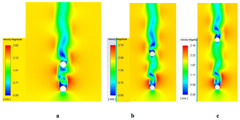
Bladeless wind turbines are attracting attention as energy harvesters due to several conveniences like the ease of construction and suitability for operating under small wind speed. As a grouped energy generation system, it is likely the simplest configuration compared to wind farms. However, the characterization of tandem harvesters requires a deep understanding of the effects produced by the interaction of the two. Therefore, this work considered a set of two conical cylinders representing tandem harvesters, which lie on the bottom of a wind tunnel and were subjected to resonance conditions. The attention focused on evaluating the effects of separation distance between conical cylinders by three distances: $\ell$ = 0.25h, 0.5h, and 0.75h, where h is the cylinder's total height. Oscillation due to vortex shedding was numerically predicted. The analysis centered on the fluid-structure interaction in pairs of wind generators subjected to wind-induced resonance, and how the distance between them affects their oscillation. Experimental data of cylinder vibration measured in a wind tunnel served to validate the numerical results. The results showed strong effects of the wake on the second cylinder placed downstream from the first one for a distance $\ell$ = 0.25h. In contrast, minimum effects were observed for $\ell$ = 0.5h and $\ell$ = 0.75h.
Citation: Dulce M Graciano, Fernando Z Sierra-Espinosa, Juan C García. Numerical simulation of vortex-induced vibration in a bladeless turbine: Effects of separation distance between tandem harvesters[J]. Metascience in Aerospace, 2024, 1(3): 309-328. doi: 10.3934/mina.2024014
Bladeless wind turbines are attracting attention as energy harvesters due to several conveniences like the ease of construction and suitability for operating under small wind speed. As a grouped energy generation system, it is likely the simplest configuration compared to wind farms. However, the characterization of tandem harvesters requires a deep understanding of the effects produced by the interaction of the two. Therefore, this work considered a set of two conical cylinders representing tandem harvesters, which lie on the bottom of a wind tunnel and were subjected to resonance conditions. The attention focused on evaluating the effects of separation distance between conical cylinders by three distances: $\ell$ = 0.25h, 0.5h, and 0.75h, where h is the cylinder's total height. Oscillation due to vortex shedding was numerically predicted. The analysis centered on the fluid-structure interaction in pairs of wind generators subjected to wind-induced resonance, and how the distance between them affects their oscillation. Experimental data of cylinder vibration measured in a wind tunnel served to validate the numerical results. The results showed strong effects of the wake on the second cylinder placed downstream from the first one for a distance $\ell$ = 0.25h. In contrast, minimum effects were observed for $\ell$ = 0.5h and $\ell$ = 0.75h.

| [1] |
Nair AR, Jaiswal V, McGinty TD (2018) Riser Vortex-Induced Vibrations. Encyclopedia Marit Offshore Eng 2017: 1–12. https://doi.org/10.1002/9781118476406.emoe492 doi: 10.1002/9781118476406.emoe492

|
| [2] |
Bhatt R, Alam MM (2018) Vibrations of a square cylinder submerged in a wake. J Fluid Mech 853: 301–332. https://doi.org/10.1017/jfm.2018.573 doi: 10.1017/jfm.2018.573
|
| [3] | Huang Z, Ong MC, Larsen CM (2019) Wake structures and vortex-induced forces of a controlled in-line vibrating circular cylinder. Ocean Eng 189. https://doi.org/10.1016/j.oceaneng.2019.106319 |
| [4] | Janocha MJ, Ong MC, Nystrøm PR, et al. (2021) Flow around two elastically-mounted cylinders with different diameters in tandem and staggered configurations in the subcritical Reynolds number regime. Mar Struct 76. https://doi.org/10.1016/j.marstruc.2020.102893 |
| [5] |
Li JH, Wang BF, Qiu X, et al. (2024) Vortex dynamics and boundary layer transition in flow around a rectangular cylinder with different aspect ratios at medium Reynolds number. J Fluid Mech 982: A5. https://doi.org/10.1017/jfm.2024.87 doi: 10.1017/jfm.2024.87
|
| [6] |
Muyshondt R, Nguyen T, Hassan YA, et al. (2021) Experimental measurements of the wake of a sphere at subcritical reynolds numbers. J Fluid Eng-T Asme 143: 061301. https://doi.org/10.1115/1.4049936 doi: 10.1115/1.4049936
|
| [7] |
Rahman H, Khan IA, Abbasi WS, et al. (2024) Aerodynamic characteristics and wake formation behind a pair of side-by-side rectangular cylinders using the lattice Boltzmann method. Ocean Eng 303: 117813. https://doi.org/10.1016/j.oceaneng.2024.117813 doi: 10.1016/j.oceaneng.2024.117813
|
| [8] |
Chen W, Ji C, Alam Md M, et al. (2022) Three-dimensional flow past two stationary side-by-side circular cylinders. Ocean Eng 244: 110379. https://doi.org/10.1016/j.oceaneng.2019.106319 doi: 10.1016/j.oceaneng.2019.106319
|
| [9] | Kumar A, Das S P, Tiwari S (2024) Wall effect on the wake characteristics of a transversely rotating sphere. Phys Fluids 36. https://doi.org/10.1063/5.0180332 |
| [10] | Liu H, Li H, Wang H, et al. (2024) Effects of a detached splitter on the vortex-induced vibration of a 5: 1 rectangular cylinder. Phys Fluids 36. https://doi.org/10.1063/5.0183812 |
| [11] |
Wang W, Duan P (2024) Vortex-induced vibration response of the cylinder inspired by Terebridae. Mar Structures 94: 103575. https://doi.org/10.1016/j.marstruc.2024.103575 doi: 10.1016/j.marstruc.2024.103575
|
| [12] | Ashouri A, Izadpanah E, Hekmat MH, et al. (2021) Numerical investigation on two-degree-of-freedom vortex-induced vibration of a circular cylinder in power-law fluids. J Nonnewton Fluid Mech 292. https://doi.org/10.1016/j.jnnfm.2021.104535 |
| [13] | Achenbach E (1974) Vortex Shedding from Spheres. J Fluid Mech 62. https://doi.org/10.1017/S0022112074000644 |
| [14] |
Gerrard JH (1966) The mechanics of the formation region of vortices behind bluff bodies. J Fluid Mech 25: 401–413. https://doi.org/10.1017/S0022112066001721 doi: 10.1017/S0022112066001721
|
| [15] |
Jiang H, Cheng L (2017) Strouhal-Reynolds number relationship for flow past a circular cylinder. J Fluid Mech 832: 170–188. https://doi.org/10.1017/jfm.2017.685 doi: 10.1017/jfm.2017.685
|
| [16] |
Liu Y, Liu J, Gao FP (2023) Strouhal number for boundary shear flow past a circular cylinder in the subcritical flow regime. Ocean Eng 269: 113574. https://doi.org/10.1016/j.oceaneng.2022.113574 doi: 10.1016/j.oceaneng.2022.113574
|
| [17] |
Derakhshandeh JF (2024) Wake-induced vibration of an elastic plate submerged in the wake of tandem circular cylinders. Phys Fluids 36: 033623. https://doi.org/10.1063/5.0199501 doi: 10.1063/5.0199501
|
| [18] |
Ramalingam S, Huang RF, Hsu CM (2023) Effect of crossflow oscillation Strouhal number on circular cylinder wake. Phys Fluids 35: 95118. https://doi.org/10.1063/5.0168618 doi: 10.1063/5.0168618
|
| [19] |
Wang Y, Lou M, Liang W, et al. (2024) Dynamic evolution of Strouhal number in flexible pipes coupling rotation. Int J Mech Sci 263: 108783. https://doi.org/10.1016/j.ijmecsci.2023.108783 doi: 10.1016/j.ijmecsci.2023.108783
|
| [20] | el Sheshtawy H, Toedter S, el Moctar O, et al. (2021) Experimentally investigated vortex-induced vibration of a high aspect ratio and small mass ratio circular cylinder oscillating in low reduced velocity flows. Ocean Eng 238. https://doi.org/10.1016/j.oceaneng.2021.109735 |
| [21] |
Ponta FL, Aref H (2004) Strouhal-Reynolds Number Relationship for Vortex Streets. Phys Rev Lett 93: 084501. https://doi.org/10.1103/PhysRevLett.93.084501 doi: 10.1103/PhysRevLett.93.084501
|
| [22] |
Williamson CHK, Brown GL (1998) A series in L/√Re to represent the Strouhal–Reynolds number relationship of the cylinder wake. J Fluids Struct 12: 1073–1085. https://doi.org/10.1006/jfls.1998.0184 doi: 10.1006/jfls.1998.0184
|
| [23] |
Williamson CHK (1996) Vortex Dynamics in the Cylinder Wake. Annu Rev Fluid Mech 28: 477–539. https://doi.org/10.1146/annurev.fl.28.010196.002401 doi: 10.1146/annurev.fl.28.010196.002401
|
| [24] |
Fey U, König M, Eckelmann H (1998) A new Strouhal–Reynolds-number relationship for the circular cylinder in the range 47<Re<2×10⁵. Phys Fluids 10: 1547–1549. https://doi.org/10.1063/1.869675 doi: 10.1063/1.869675
|
| [25] |
Derakhshandeh JF, Alam MM (2019) A review of bluff body wakes. Ocean Eng 182: 475–488. https://doi.org/10.1016/j.oceaneng.2019.04.093 doi: 10.1016/j.oceaneng.2019.04.093
|
| [26] | Bernitsas MM, Raghavan K, Ben-Simon Y, et al. (2006) VIVACE (Vortex Induced Vibration Aquatic Clean Energy): A New Concept in Generation of Clean and Renewable Energy From Fluid Flow. in Volume 2: Ocean Engineering and Polar and Arctic Sciences and Technology, 619–637. https://doi.org/10.1115/OMAE2006-92645 |
| [27] |
Raghavan K, Bernitsas MM (2011) Experimental investigation of Reynolds number effect on vortex induced vibration of rigid circular cylinder on elastic supports. Ocean Eng 38: 719–731. https://doi.org/10.1016/j.oceaneng.2010.09.003 doi: 10.1016/j.oceaneng.2010.09.003
|
| [28] | Villarreal Yañez DJ (2018) Vortex resonance wind turbine. Available from: https://www.researchgate.net/profile/David-J-Yanez/publication/. |
| [29] |
Chizfahm A, Yazdi EA, Eghtesad M (2018) Dynamic modeling of vortex induced vibration wind turbines. Renew Energ 121: 632–643. https://doi.org/10.1016/j.renene.2018.01.038 doi: 10.1016/j.renene.2018.01.038
|
| [30] |
González-González E, Yáñez DJ, Del Pozo S, et al. (2024) Optimizing Bladeless Wind Turbines: Morphological Analysis and Lock-In Range Variations. Appl Sci 14: 2815. https://doi.org/10.3390/app14072815 doi: 10.3390/app14072815
|
| [31] |
Sun H, Ma C, Kim ES, et al. (2017) Hydrokinetic energy conversion by two rough tandem-cylinders in flow induced motions: Effect of spacing and stiffness. Renew Energ 107: 61–80. https://doi.org/10.1016/j.renene.2017.01.043 doi: 10.1016/j.renene.2017.01.043
|
| [32] |
Lam K, Fang X (1995) The Effect of Interference of Four Equispaced Cylinders in Cross Flow on Pressure and Force Coefficients. J Fluids Struct 9: 195–214. https://doi.org/10.1006/jfls.1995.1010 doi: 10.1006/jfls.1995.1010
|
| [33] |
Lam K, Li JY, So RMC (2003) Force coefficients and Strouhal numbers of four cylinders in cross flow. J Fluids Struct 18: 305–324. https://doi.org/10.1016/j.jfluidstructs.2003.07.008 doi: 10.1016/j.jfluidstructs.2003.07.008
|
| [34] |
Zou L, Lin Y, Lam K (2008) Large-Eddy Simulation of Flow Around Cylinder Arrays at a Subcritical Reynolds Number. J Hydrodyn 20: 403–413. https://doi.org/10.1016/j.jfluidstructs.2003.07.008 doi: 10.1016/j.jfluidstructs.2003.07.008
|
| [35] |
Kahil Y, Benhamadouche S, Berrouk AS, et al. (2019) Simulation of subcritical-Reynolds-number flow around four cylinders in square arrangement configuration using LES. Eur J Mech-B/Fluids 74: 111–122. https://doi.org/10.1016/j.euromechflu.2018.11.008 doi: 10.1016/j.euromechflu.2018.11.008
|
| [36] |
Pouryoussefi SG, Mirzaei M, Pouryoussefi SMH (2011) Force coefficients and Strouhal numbers of three circular cylinders subjected to a cross-flow. Arch Appl Mech 81: 1725–1741. https://doi.org/10.1007/s00419-011-0514-3 doi: 10.1007/s00419-011-0514-3
|
| [37] | Kim S, Alam MM, Sakamoto H, et al. (2009) Flow-induced vibrations of two circular cylinders in tandem arrangement. Part 1: Characteristics of vibration. J Wind Eng Ind Aerod 97: 304–311. https://doi.org/10.1016/j.jweia.2009.07.004 |
| [38] |
Xu W, Ji C, Sun H, et al. (2019) Flow-induced vibration of two elastically mounted tandem cylinders in cross-flow at subcritical Reynolds numbers. Ocean Eng 173: 375–387. https://doi.org/10.1016/j.oceaneng.2019.01.016 doi: 10.1016/j.oceaneng.2019.01.016
|
| [39] |
Assi GRS, Bearman PW, Carmo BS, et al. (2013) The role of wake stiffness on the wake-induced vibration of the downstream cylinder of a tandem pair. J Fluid Mech 718: 210–245. https://doi.org/10.1017/jfm.2012.606 doi: 10.1017/jfm.2012.606
|
| [40] |
Kim ES, Bernitsas MM (2016) Performance prediction of horizontal hydrokinetic energy converter using multiple-cylinder synergy in flow induced motion. Appl Energ 170: 92–100. https://doi.org/10.1016/j.apenergy.2016.02.116 doi: 10.1016/j.apenergy.2016.02.116
|
| [41] | Kim ES, Bernitsas MM, Kumar RA (2011) Multi-Cylinder Flow-Induced Motions: Enhancement by Passive Turbulence Control at 28, 000<Re<120, 000. in Volume 7: CFD and VIV; Offshore Geotechnics, 249–260. https://doi.org/10.1115/OMAE2011-49405 |
| [42] | Ding L, Bernitsas MM, Kim ES (2013) 2-D URANS vs. experiments of flow induced motions of two circular cylinders in tandem with passive turbulence control for 30, 000<Re<105, 000. Ocean Eng 72: 429–440. https://doi.org/10.1016/j.oceaneng.2013.06.005 |
| [43] | Vandiver KJ, Cheng Y, Jaiswal V, et al. (2009) An experimental evaluation of vortex-induced vibration of a riser bundle with gaps. Proc of the ASME 28th Int Conf on Ocean, Offshore and Arctic Engineering, Honolulu. https://doi.org/10.1115/OMAE2009-79757 |
| [44] | Haider BA, Sohn CH (2018) Effect of spacing on a pair of naturally oscillating circular cylinders in tandem arrangements employing IB-LB methods: Crossflow-induced vibrations. Int J Mech Sci 142–143, 74–85. https://doi.org/10.1016/j.ijmecsci.2018.04.032 |
| [45] |
Song R, Shan X, Lv F, et al. (2015) A study of vortex-induced energy harvesting from water using PZT piezoelectric cantilever with cylindrical extension. Ceram Int 41: S768–S773. https://doi.org/10.1016/j.ceramint.2015.03.262 doi: 10.1016/j.ceramint.2015.03.262
|
| [46] |
Lai Z, Wang S, Zhu L, et al. (2021) A hybrid piezo-dielectric wind energy harvester for high-performance vortex-induced vibration energy harvesting. Mech Syst Signal Process 150: 107212. https://doi.org/10.1016/j.ymssp.2020.107212 doi: 10.1016/j.ymssp.2020.107212
|
| [47] |
Yuan W, Sun H, Li H, et al. (2020) Flow-induced oscillation patterns for two tandem cylinders with turbulence stimulation and variable stiffness and damping. Ocean Eng 218: 108237. https://doi.org/10.1016/j.oceaneng.2020.108237 doi: 10.1016/j.oceaneng.2020.108237
|
| [48] |
Williamson CHK, Govardhan R (2004) VORTEX-INDUCED VIBRATIONS. Annu Rev Fluid Mech 36: 413–455. https://doi.org/10.1146/annurev.fluid.36.050802.122128 doi: 10.1146/annurev.fluid.36.050802.122128
|
| [49] |
Govardhan R, Williamson CHK (2000) Modes of vortex formation and frequency response of a freely vibrating cylinder. J Fluid Mech 420: 85–130. https://doi.org/10.1017/S0022112000001233 doi: 10.1017/S0022112000001233
|
| [50] | Cajas JC, Pastrana D, Rodríguez I, et al. (2021) Vortex induced vibrations of a pivoted finite height cylinder at low Reynolds number. Phys Fluid 33. http://doi.org/10.1063/5.0051689 |
| [51] | Kara MC, Jaiswal V, Sharma PP, et al. (2018) Numerical Modeling of High Length-to-Diameter Ratio Riser Subjected to VIV. Paper presented at the Offshore Technology Conference, Houston, Texas, USA. https://doi.org/10.4043/28635-MS |
| [52] | Ferziger J, Peric M (1996) Computational methods for fluid dynamics, Springer-Verlag, Berlin Heidelberg. https://doi.org/10.1007/978-3-319-99693-6 |
| [53] | Graciano DM (2020) Determination of the wake vortex effect on the oscillation of a group of wind generators by vorticity, Master Thesis, State of Morelos University, Center for Research in Engineering and Applied Sciences, UAEM, Cuernavaca, Mexico. |
| [54] | Goldstein S (1938) Modern developments in fluid dynamics; an account of theory and experiment relating to boundary layers, turbulent motion and wakes. Oxford: Cambridge University Press. |

Figures(10) / Tables(5)
Dulce M Graciano, Fernando Z Sierra-Espinosa, Juan C García. Numerical simulation of vortex-induced vibration in a bladeless turbine: Effects of separation distance between tandem harvesters[J]. Metascience in Aerospace, 2024, 1(3): 309-328. doi: 10.3934/mina.2024014


 DownLoad: