Microwave (MW) irradiation is recognized as an effective tool in industries related to pharmaceuticals, chemistry, nanoparticle synthesis, food, etc. In the hardware field, some research efforts are concentrated on creating miniature reactors using low-cost technologies aimed at on-demand chemistry or parallel synthesis of many drugs.
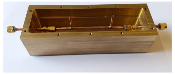
This paper reports on the development and characterization of novel miniature chemical-resistant glass-metal coaxial reactors based on a modified Liebig condenser. It is composed of two concentric glass tubes, one for the central conductor carrying MW current, and the other for the copper-foiled cylinder surrounding the first pipe. The gap between them is filled with a liquid that is pumped and evacuated by using shielded thin inlet/outlet glass tubes, which are melted and opened into this cylindrical cavity. The reactor's geometry allows for the direct soldering of miniature MW SMA coaxial connectors of 50-Ω impedance.
The developed components are studied analytically, numerically and experimentally. The frequency properties of reactors are measured with a network analyzer. The temperature trends are explored by using a variable high-power MW generator, power meters and temperature sensors.
These reactors demonstrate their relative insensitivity toward variations in the permittivity of filling liquids in the range of $3.75 < \varepsilon < 30$, as shown in simulations and measurements. They demonstrate the increase by two orders in the longitudinal modal penetration depth and a more homogeneous heating along reactors as compared to their hollow coaxial prototypes.
These glass-metal miniature reactors can be used in on-demand continuous-flow accelerated liquid heating, chemistry and pharmacy.
Citation: Gaurav Sharma, Guennadi A. Kouzaev. Miniature glass-metal coaxial waveguide reactors for microwave-assisted liquid heating[J]. AIMS Electronics and Electrical Engineering, 2023, 7(1): 100-120. doi: 10.3934/electreng.2023006
Microwave (MW) irradiation is recognized as an effective tool in industries related to pharmaceuticals, chemistry, nanoparticle synthesis, food, etc. In the hardware field, some research efforts are concentrated on creating miniature reactors using low-cost technologies aimed at on-demand chemistry or parallel synthesis of many drugs.
This paper reports on the development and characterization of novel miniature chemical-resistant glass-metal coaxial reactors based on a modified Liebig condenser. It is composed of two concentric glass tubes, one for the central conductor carrying MW current, and the other for the copper-foiled cylinder surrounding the first pipe. The gap between them is filled with a liquid that is pumped and evacuated by using shielded thin inlet/outlet glass tubes, which are melted and opened into this cylindrical cavity. The reactor's geometry allows for the direct soldering of miniature MW SMA coaxial connectors of 50-Ω impedance.
The developed components are studied analytically, numerically and experimentally. The frequency properties of reactors are measured with a network analyzer. The temperature trends are explored by using a variable high-power MW generator, power meters and temperature sensors.
These reactors demonstrate their relative insensitivity toward variations in the permittivity of filling liquids in the range of $3.75 < \varepsilon < 30$, as shown in simulations and measurements. They demonstrate the increase by two orders in the longitudinal modal penetration depth and a more homogeneous heating along reactors as compared to their hollow coaxial prototypes.
These glass-metal miniature reactors can be used in on-demand continuous-flow accelerated liquid heating, chemistry and pharmacy.

| [1] | Loupy A (2006) Microwaves in Organic Synthesis. Weinheim: Wiley-VCH. https://doi.org/10.1002/9783527619559 |
| [2] | Kappe C, Stadler A, Dallinger D (2012) Microwaves in Organic and Medicinal Chemistry. Weinheim: Wiley-VCH. https://doi.org/10.1002/3527606556 |
| [3] | Metaxas A, Meredith R (2008) Industrial Microwave Heating. Milton Keynes, UK: Lightning Source UK Ltd. |
| [4] |
Li M, Wu X, Han D, et al. (2022) A high-efficiency single-mode traveling wave reactor for continuous flow processing. Processes 10: 1261. https://doi.org/10.3390/pr10071261 doi: 10.3390/pr10071261

|
| [5] | Nikawa Y (2016) Measurement of temperature dependent permittivity of liquid under microwave heating. Proc 2016 IEEE MTT-S Int Microw Symp (IMS), 1‒4. https://doi.org/10.1109/MWSYM.2016.7540089 |
| [6] |
Miyakawa M, Kanamori S, Hagihara K, et al. (2021) Cylindrical resonator-type microwave heating reactor with real-time monitoring function of dielectric property applied to drying processes. Ind Eng Chem Res 60: 9119–9127. https://doi.org/10.1021/acs.iecr.1c00569 doi: 10.1021/acs.iecr.1c00569
|
| [7] |
Topcam H, Karatas O, Erol B, et al. (2020) Effect of rotation on temperature uniformity of microwave processed low-high viscosity liquids: A computational study with experimental validation. Innov Food Sci Emerg 60: 102306. https://doi.org/10.1016/j.ifset.2020.102306 doi: 10.1016/j.ifset.2020.102306
|
| [8] |
Navarro M (2020) Water, toluene, and ethanol under microwave irradiation: numerical simulations of the effect of the vessel's size. J Heat Transfer 142: 102104. https://doi.org/10.1115/1.4047512 doi: 10.1115/1.4047512
|
| [9] |
Son E, Coskun E, Ozturk S, et al. (2022) Microwave decontamination process for hummus: A computational study with experimental validation. Innov Food Sci Emerg 82: 103162. https://doi.org/10.1016/j.ifset.2022.103162 doi: 10.1016/j.ifset.2022.103162
|
| [10] |
Khaghanikavkani E, Farid M, Holdem J, et al. (2013) Microwave pyrolysis of plastic. J Chem Eng Process Techn 4: 1000150. https://doi.org/10.4172/2157-7048.1000150 doi: 10.4172/2157-7048.1000150
|
| [11] |
Mitani T, Hasegawa N, Nakajima R, et al. (2016) Development of a wideband microwave reactor with a coaxial cable. Chem Eng J 299: 209‒216. http://dx.doi.org/10.1016/j.cej.2016.04.064 doi: 10.1016/j.cej.2016.04.064
|
| [12] | Kapranov S, Kouzaev G (2015) Scalable reactor for microwave-and ultrasound-assisted chemistry. GB Patent Appl. GB1504690.7A dated on 2015-03-19. IPO Patent Searchable Patents J 6572: dated 06.05.2015. Available from: https://patents.google.com/patent/GB2536485A/en?inventor=Kouzaev+Guennadi |
| [13] |
Kapranov S, Kouzaev G (2017) Models of water, methanol, and ethanol and their applications in the design of miniature microwave heating reactors. Int J Thermal Sci 122: 53‒73. https://doi.org/10.1016/j.ijthermalsci.2017.08.007 doi: 10.1016/j.ijthermalsci.2017.08.007
|
| [14] | Kouzaev G (2017) A method and apparatus for separate supply of microwave and mechanical energies to liquid reagents in coaxial rotating chemical reactors. GB Patent Appl. GB1704095.7 dated 15 March 2017. IPO Patent Searchable Patents J 6675 dated 26.04.2017. Available from: https://patents.google.com/patent/GB2560545A/en |
| [15] |
Kapranov S, Kouzaev G (2019) Study of microwave heating of reference liquids in a coaxial waveguide reactor using the experimental, semi-analytical, and numerical means. Int J Thermal Sci 140: 505‒520. https://doi.org/10.1016/j.ijthermalsci.2019.03.023 doi: 10.1016/j.ijthermalsci.2019.03.023
|
| [16] |
Kouzaev G, Kapranov S (2020) Microwave miniature coaxial reactors for on-demand material synthesis. TechRxiv Preprint. https://doi.org/10.36227/techrxiv.11649678.v2 doi: 10.36227/techrxiv.11649678.v2
|
| [17] |
Sarabi F, Chorbani M, Stankiewicz A, et al. (2020) Coaxial traveling-wave microwave reactors: Design challenges and solutions. Chem Eng Res Design 153: 677‒683. https://doi.org/10.1016/j.cherd.2019.11.022 doi: 10.1016/j.cherd.2019.11.022
|
| [18] |
Kouzaev G (2022) Glass-metal coaxial-waveguide reactors for on-demand microwave-assisted chemistry. TechRxiv Preprint. https://doi.org/10.36227/techrxiv.20045006.v2 doi: 10.36227/techrxiv.20045006.v2
|
| [19] |
Shi WD, Wang C, and Yan WC (2022) Model-based design and operation of coaxial-probe-type microwave reactor toward large-scale production of nanoparticles. Chem Eng Sci 264: 118162. https://doi.org/10.1016/j.ces.2022.118162 doi: 10.1016/j.ces.2022.118162
|
| [20] |
Shah J, Sundaresan S, Geist J, et al. (2007) Microwave dielectric heating of fluids in an integrated microfluidic device. J Micromech Microeng 17: 2224‒2230. https://doi.org/10.5772/53881 doi: 10.5772/53881
|
| [21] |
Issadore D, Humphry K, Brown K, et al. (2009) Microwave dielectric heating of drops in microfluidic devices. Lab Chip 9: 1701‒1706. https://doi.org/10.1039/b822357b doi: 10.1039/b822357b
|
| [22] |
Khayari A, Medrano M, Verlagio E, et al. (2011) Microwave-induced water flow in a microchannel built on a coplanar waveguide. J Appl Phys 110: 064912. https://doi.org/10.1063/1.3641516 doi: 10.1063/1.3641516
|
| [23] |
Koziej D, Floryan C, Spering R, et al. (2013) Microwave dielectric heating of non-aqueous droplets in a microfluidic device for nanoparticle synthesis. Nanoscale 5: 5468‒5475. https://doi.org/10.1039/C3NR00500C doi: 10.1039/C3NR00500C
|
| [24] |
Mascia S, Heider P, Zhang H (2013) End-to-end continuous manufacturing of pharmaceuticals: integrated synthesis, purification, and final dosage formation. Angew Chem Int Ed 52: 12359‒12363. https://doi.org/10.1002/anie.201305429 doi: 10.1002/anie.201305429
|
| [25] |
Li J, Ballmer S, Gillis E, et al. (2015) Synthesis of many different types of small organic molecules using one automated process. Science 347: 1221‒1226. http://dx.doi.org/10.1126/science.aaa5414 doi: 10.1126/science.aaa5414
|
| [26] |
Kitson P, Marie G, Francoia J, et al. (2018) Digitization of multistep organic synthesis in reactionware for on-demand pharmaceuticals. Science 359: 314‒319. https://doi.org/10.1126/science.aao3466 doi: 10.1126/science.aao3466
|
| [27] |
Shibata K, Kobayashi M (2015) Measurement of complex permittivity for liquids using the coaxial line reflection method. Proc APEEMC'2015, 452‒455. https://doi.org/10.1109/APEMC.2015.7175237 doi: 10.1109/APEMC.2015.7175237
|
| [28] |
Jensen W (2006) The origin of the Liebig condenser. J Chem Educ 83: 23. https://doi.org/10.1021/ed083p23 doi: 10.1021/ed083p23
|
| [29] | RG401 Coax Cable. Technical Data Sheet. 2022. Available from: https://www.pasternack.com/images/ProductPDF/RG401-U-FT.pdf |
| [30] | Ott H (2009) Electromagnetic Compatibility Engineering. NY: J. Wiley & Sons. |
| [31] | Shielding Effectiveness of Expanded Metal Foils (EMFs). Dexmet Corp. 2022. Available from: https://cdn2.hubspot.net/hubfs/3798930/assets/PDF%20files/Shielding_Effectiveness_82017.pdf |
| [32] | Kouzaev G (2013) Applications of Advanced Electromagnetics. Components and Systems. Berlin Heidelberg: Springer Verlag. |
| [33] |
Mcintosh R, Turgeon L (1973) Propagation along transversely inhomogeneous coaxial transmission lines. IEEE T Microw Theory 21: 139‒142. https://doi.org/10.1109/TMTT.1973.1127949 doi: 10.1109/TMTT.1973.1127949
|
| [34] |
Mitelman Y (2019) A novel method for inhomogeneous coaxial line analysis. Proc 2019 Ural Symp Biomedical Eng., Radioelectronics and Inform Technology (USBERIT), 458‒461. https://doi.org/10.1109/USBEREIT.2019.8736605 doi: 10.1109/USBEREIT.2019.8736605
|
| [35] |
Wand W, Al-Charchafchi S (1998) Using equivalent dielectric constant to simplify the analysis of patch microstrip antenna with multi layer substrate. IEEE Antenn Propag Soc Int Symp, Digest 2: 676‒679. https://doi.org/10.1109/APS.1998.702028 doi: 10.1109/APS.1998.702028
|
| [36] | Nikol'skii V, Nikol'skaia T (1989) Electrodynamics and Radiowave Propagation. Moscow: Nauka Publ. (in Russian). |
| [37] | Gunston M (1972) Microwave Transmission-Line Impedance Data. NY: Van Nostrand Reinhold Comp. Ltd. |
| [38] | Comsol Multiphysics. Available from https://www.comsol.com |
| [39] | Komarov V (2012) Handbook of Dielectric and Thermal Properties of Materials at Microwave Frequencies. Artech House. |
| [40] |
Michalski K, Mustafa M (2018) On the computation of hybrid modes in planar layered waveguides anisotropic conductive sheets with multiple anisotropic conductive sheets. Proc R Soc A 474: 20180288. http://dx.doi.org/10.1098/rspa.2018.0288 doi: 10.1098/rspa.2018.0288
|
| [41] |
Tyszkiewicz C (2012) Sensing properties of four-layered planar waveguide design. Theoretical analyses. Acta Polonica A 122: 908‒914. https://doi.org/10.12693/APhysPolA.122.908 doi: 10.12693/APhysPolA.122.908
|
| [42] | Sengwa R, Kaur K, Chaudhary R (2000) Dielectric properties of low molecular weight poly(ethylene glycol)s. Polymer Int 49: 599‒608. |
| [43] | Dielectric properties of solvents. 2022. Available from: https://cem.com/cn/microwave-chemistry/solvent-choice |
| [44] | Gupta K, Garg R, Chadha R (1981) Computer-aided Design of Microwave Circuits. Artech House. |
| [45] |
Bao JZ (1996) Microwave dielectric characterization of binary mixtures of water, methanol, and ethanol. J Chem Phys 104: 4441. https://doi.org/10.1063/1.471197 doi: 10.1063/1.471197
|


Figures(16) / Tables(1)

Gaurav Sharma, Guennadi A. Kouzaev. Miniature glass-metal coaxial waveguide reactors for microwave-assisted liquid heating[J]. AIMS Electronics and Electrical Engineering, 2023, 7(1): 100-120. doi: 10.3934/electreng.2023006


 DownLoad: