Research article

Electrochemical Cs removal and crystal formation from Fukushima weathered biotite in molten NaCl-CaCl2

  • Received: 28 November 2018 Accepted: 03 March 2019 Published: 19 March 2019
  • The possibility of removal and controlling crystal formation from weathered biotite (WB) in clay minerals were investigated using molten salt electrochemistry (EC) in molten NaCl-CaCl2 under an electrochemical reductive reaction. Cyclic Voltammogram (CV) measurements were performed in the range of +0.5 V to −2.2 V. Several peaks were confirmed in the CV spectra. The peak at −1.4 V represents a reduction reaction of Fe in WB, so we conducted an experiment at −1.4 V for 2 h to reduce Iron (Fe). The Cs removal rate after EC treatment was determined by X-ray fluorescence analysis, and almost 100% Cs removal was confirmed. To understand the effect of the reductive reaction, we performed X-ray Adsorption Fine Structure (XAFS) analysis. Before EC treatment, the Fe in WB was present as a mixture of Fe3+ and Fe2+. After EC treatment, the presence of Fe2+ was confirmed by XAFS analysis. Based on this finding, EC treatment is effective for reducing Fe in WB. This result indicated that Fe2O3 formation was suppressed, and the reduction reaction was effective for controlling crystal formation.

    Citation: M. Honda, T. Goto, Y. Sakanaka, T. Yaita, S. Suzuki. Electrochemical Cs removal and crystal formation from Fukushima weathered biotite in molten NaCl-CaCl2[J]. AIMS Electronics and Electrical Engineering, 2019, 3(2): 102-110. doi: 10.3934/ElectrEng.2019.2.102

    Related Papers:

    [1] Abderraouf Fadhel, Souad Berhab, Rahma Aloulou, Hassene Mnif, Abdennour Belhedri . Compact modified rectangular split ring resonator for tri-band satellite applications. AIMS Electronics and Electrical Engineering, 2024, 8(4): 466-487. doi: 10.3934/electreng.2024022
    [2] Sandeep Kumar Singh, Tripurari Sharan, Arvind Kumar Singh . Investigating the S-parameter (|S11|) of CPW-fed antenna using four different dielectric substrate materials for RF multiband applications. AIMS Electronics and Electrical Engineering, 2022, 6(3): 198-222. doi: 10.3934/electreng.2022013
    [3] Hakkee Jung . Analytical models of threshold voltage and drain induced barrier lowering in junctionless cylindrical surrounding gate (JLCSG) MOSFET using stacked high-k oxide. AIMS Electronics and Electrical Engineering, 2022, 6(2): 108-123. doi: 10.3934/electreng.2022007
    [4] Jing Ou, Yingzhen Liu, Martin Doppelbauer . Torque analysis and slot regions assignment of a DC-excited flux-modulated machine with two stator windings. AIMS Electronics and Electrical Engineering, 2017, 1(1): 4-17. doi: 10.3934/ElectrEng.2017.1.4
    [5] Mostafa A.R. Eltokhy, Mohamed Abdel-Hady, Ayman Haggag, Hisham A. Hamad, Tarek Hosny, Ahmed A. F. Youssef, Ali M. El-Rifaie . An indoor IoT-based LiFi system using LEDs for sensor data transfer. AIMS Electronics and Electrical Engineering, 2025, 9(2): 118-138. doi: 10.3934/electreng.2025007
    [6] Shaswat Chirantan, Bibhuti Bhusan Pati . Integration of predictive and computational intelligent techniques: A hybrid optimization mechanism for PMSM dynamics reinforcement. AIMS Electronics and Electrical Engineering, 2024, 8(2): 265-291. doi: 10.3934/electreng.2024012
    [7] Youness Chawki, Khalid Elasnaoui, Mohamed Ouhda . Classification and detection of Covid-19 based on X-Ray and CT images using deep learning and machine learning techniques: A bibliometric analysis. AIMS Electronics and Electrical Engineering, 2024, 8(1): 71-103. doi: 10.3934/electreng.2024004
    [8] Hakkee Jung . Analytical model of subthreshold swing in junctionless gate-all-around (GAA) FET with ferroelectric. AIMS Electronics and Electrical Engineering, 2023, 7(4): 322-336. doi: 10.3934/electreng.2023017
    [9] Hakkee Jung . Analysis of drain induced barrier lowering for junctionless double gate MOSFET using ferroelectric negative capacitance effect. AIMS Electronics and Electrical Engineering, 2023, 7(1): 38-49. doi: 10.3934/electreng.2023003
    [10] Jun Yoneyama . H disturbance attenuation of nonlinear networked control systems via Takagi-Sugeno fuzzy model. AIMS Electronics and Electrical Engineering, 2019, 3(3): 257-273. doi: 10.3934/ElectrEng.2019.3.257
  • The possibility of removal and controlling crystal formation from weathered biotite (WB) in clay minerals were investigated using molten salt electrochemistry (EC) in molten NaCl-CaCl2 under an electrochemical reductive reaction. Cyclic Voltammogram (CV) measurements were performed in the range of +0.5 V to −2.2 V. Several peaks were confirmed in the CV spectra. The peak at −1.4 V represents a reduction reaction of Fe in WB, so we conducted an experiment at −1.4 V for 2 h to reduce Iron (Fe). The Cs removal rate after EC treatment was determined by X-ray fluorescence analysis, and almost 100% Cs removal was confirmed. To understand the effect of the reductive reaction, we performed X-ray Adsorption Fine Structure (XAFS) analysis. Before EC treatment, the Fe in WB was present as a mixture of Fe3+ and Fe2+. After EC treatment, the presence of Fe2+ was confirmed by XAFS analysis. Based on this finding, EC treatment is effective for reducing Fe in WB. This result indicated that Fe2O3 formation was suppressed, and the reduction reaction was effective for controlling crystal formation.


    A large quantity of radioactive nuclides was scattered by the Fukushima Daiichi Nuclear Power Plant accident (Hereinafter: 1F) that occurred in March 2011. More than 22 million m3 of radioactive contaminated soil was placed in temporary storage space during decontamination of the land. Therefore, volume reduction of the contaminated soil is an emergent challenge [1,2,3,4,5,6,7,8]. To overcome this challenge, several volume-reduction technologies have been developed thus far. The existing technologies are classified into three categories, namely, grading, chemical processing, heat treatment. These technologies have unique advantages and disadvantages. For example, the cost of grading is lower than the costs of the other techniques, but its radionuclide removal rate is not very high. Herein, we focus on heat treatment. Heat treatment is a highly efficient soil decontamination method [9]. The basic concept is the addition of an alkali chloride to the soil along with heat. However, the processing cost associated with this technique is higher than that of the other techniques. Therefore, to lower the total cost, it is essential to develop recycling technology. To solve this problem, we are promoting the research and development of a new heat treatment method.

    Cs adsorbs strongly on weathered biotite (hereinafter WB), as reported by Mukai et al. [10]. We demonstrated this using WB. We found that more than 99% of Cs can be removed by means of heat treatment [11]. After Cs was removed, the WB decomposed and four types of crystals were formed that were namely calcite, hematite, augite, and wadalite [12]. In addition, we recorded X-Ray Diffraction (XRD) patterns of WB after heat treatment at several temperatures. The pattern recorded at 400 ℃ was almost the same as that before heating. By contrast, several new peaks were observed in the pattern recorded at 500 ℃. Additional new peaks appeared after heat treatment in the pattern recorded at 600 ℃. Furthermore, the peak that appeared at 8° disappeared after heat treatment at 700 ℃. The disappearance of this peak indicates that the silicate structure in WB was decomposed completely. After the WB was decomposed, calcite, wadalite, hematite, and augite were formed, and it is known that these materials are effective for use in industrial applications. When we consider the effective use of these materials, further improvement of selectivity is necessary for the application as energy materials. Therefore, in this study, we attempt to establish a new heat treatment method called the molten salt electrochemical method (EC). Specifically, we focus on Fe in WB. Fe is one of the most important elements in WB. The proposed EC method can control the redox reaction in molten salt, and it is expected that by using this method, novel materials with unique functional properties can be synthesized. To verify the effectiveness of the EC method, we investigate Cs removal and structural changes in WB as a result of the proposed heat treatment scheme by using X-ray fluorescence (XRF), XRD, X-ray Adsorption Fine Structure (XAFS) analysis, and Scanning Electron Microscopy-Energy-Dispersive X-ray (SEM-EDX) spectroscopy. Accordingly, the purposes of this study are as follows.

    1. Can crystal formation be controlled using the proposed EC method?

    2. What changes can be found in the products owing to the reductive reaction?

    The apparatus used to execute the EC method was installed in a heat treatment system. The EC method is among the attractive methods available for fabricating metal and semiconductor films. Herein, we attempt to reduce Fe in WB, a clay mineral, by using the EC method. In general, clay minerals can be regarded as metal oxides. Fe is one of the most geologically important elements, and it is often present in clay minerals. If we can reduce Fe by using EC method, we can alter the crystals formed after the decomposition of WB.

    The experimental setup is shown in Figure 1(a). "A" is Ar gas IN, "B" is Glassy Carbon counter electrode, "C" is Platinum working electrode, "D" is Ag/AgCl reference electrode, "E" is Ar gas OUT, "F" is quartz cell and "G" is molten NaCl-CaCl2. Figure 1(b) shows the photograph of electrochemical system. Figure 1(c) shows photographs of the Pt electrode before and after the reaction. In EC, three electrodes are used in molten NaCl-CaCl2. We used a Pt mesh electrode at the working electrode (W.E.), and its surface area was kept large to ensure effective reaction in molten salt. Glassy carbon rods were used as counter electrodes (C.E.). An Ag wire coated with Al2O3 was used as the reference electrode (R.E.). We prepared and compared three types of samples. Sample (1) is WB only. Sample (2) is WB with added mixed salt(NaCl-CaCl2) and heat-treated at 700 ℃. Sample (3) is WB with added mixed salt (NaCl-CaCl2) and heat-treated at 700 ℃ under reductive potential treatment at −1.4 V. 40 mg of mixed salt NaCl-CaCl2 with molar ration 1:1 was added to 40 mg of WB powder. After natural cooling, the sample was dispersed in 50 mL of distilled water by ultra-sonication. It was then subjected to centrifugal separation at 6000 rpm for 30 min. After the supernatant liquid was removed, the sediment was dried on a hot plate at approximately 100 ℃.

    Figure 1.  (a) Schematic diagram of electrochemical method in molten salt. (b) Photograph of electrochemical system and (c) Pt mesh electrode before and after reaction.

    The electrochemical conditions were as follows: temperature = 700 ℃ for 2 h; scan range = −2.2 V to +0.5 V; and scan rate = 100 mV/s. The reductive potential was −1.4 V owing to the Fe reduction reaction. Composition of sample was conducted by XRF (Shimadzu EDX-8100), and structural analysis was conducted by XRD (Rigaku Smart Lab Ⅱ) using Ni-filtered Cu Kα radiation. XAFS measurement was conducted at BL-27B hard X-ray beamline at the Photon Factory of High Energy Research Organization (KEK-PF).

    To control the reaction of Fe (Iron) in the clay mineral, cyclic voltammetry (CV) and chronoamperometry (CA) were conducted. Figure 2(a) shows the CV from +0.5 V to −2.2 V. It is recorded at the begging of the procedure. Several types of peaks were confirmed at a & a', b & b', and c. Peak a & a' corresponding to the reductive potential around −1.4 V was considered with reduction potential of Si and Fe elements included in soil because WB was turned to augite, wadalite, and hematite in molten NaCl-CaCl2 at 700 ℃. B and B' peaks corresponding to the calcium redox reaction in molten salt were identified. Peak C represented the oxidation reaction during EC treatment because EC was conducted in atmosphere in this study.

    Figure 2.  (a) Cyclic voltammogram for a Pt electrode in NaCl-CaCl2 at 700 ℃. Scanning rate: 0.1Vs-1. (b) Chronoamperometry at 700 ℃.

    The panel on the right in Figure 2(b) shows the chronoamperometry result. Chronoamperometry is a time-dependent technique. In this study, we checked only whether the potential of the working electrode was stepped at 700 ℃ and maintained for 2 h. To investigate the changes caused by molten salt EC, we performed XRF measurement.

    Figure 3 shows the result of XRF analysis. We confirmed the Cs removal ratio and the composition changes after the heat treatment and EC treatment. The initial composition of the WB sample and after heat treatment and EC treatment is also summarized in Table 1. The main components include Si, Al, and Fe. Ca is present in small amounts, and Cl is absent. We focused on changes in the quantities of Cs, K, Ca, and Cl. In case of EC treatment, Ni was slightly detected because a Ni wire is used for a part to connect a Pt electrode (shown as Figure 1(a)-(c). It is considered that Ni slightly melted in the process of EC treatment.

    Figure 3.  Cs/Si, K/Si, Ca/Si, and Cl/Si of three types of samples, as determined by XRF.
    Table 1.  Components of WB, WB+mixed salt/700 ℃, and WB+mixed salt/700 ℃ after EC treatment as determined by XRF.
    Element SiO2 Al2O3 Fe2O3 MgO K2O CsO2 TiO2 CaO Cl Ni
    WB 43.0 18.9 16.9 7.4 5.1 4.9 2.3 0.9 n.d n.d
    WB+mixed salt / 700 ℃ 34.1 16.1 11.2 6.7 0.47 n.d 2.2 25.5 3.4 n.d
    WB+mixed salt / 700 ℃ after EC treatment 33.0 10.9 11.3 4.8 0.34 n.d 1.4 32.5 0.35 2.6

     | Show Table
    DownLoad: CSV

    Figure 3(a) shows the molar ratios of Cs and K in three types of samples, as obtained by XRF analysis. (1)The black bar shows the initial values about WB. (2)The red bar shows the results after heat treatment at 700 ℃, and (3) the blue bar shows the molar ratios of Cs and K under application of −1.4 V. In these results, Cs is completely removed from WB (meaning Cs is under the detection limit) both sample (2) and (3). We confirmed that K shows the same tendency as Cs. By contrast, Ca and Cl show remarkably different behaviors. Figure 3(b) shows the molar ratios of Ca and Cl. Ca is initially present in small quantities in WB. Cl is absent. However, after the heat and EC treatment, the quantities of Ca and Cl increase drastically. This result seems to imply that Ca and Cl are involved in the silicate structure.

    To understand the structural changes in the three types of samples, we conducted XRD analysis. Figure 4 shows the XRD patterns of these samples. (1)The black line represents WB, and (2) the red line represents WB heat-treated at 700 ℃, and (3) the blue line represents WB subjected to EC treatment (−1.4 V) heat-treated at 700 ℃. First, we confirmed that the peak at 8° is due to XRD from silicate structure at WB [13]. Second, the silicate structure decomposed completely after heat treatment at 700 ℃. In the case of EC treatment (−1.4 V), too, the silicate structure decomposed. In addition, a new XRD pattern appeared at 18° and 23°. This pattern is quite different from that recorded at heat-treated at 700 ℃. These results indicate that different crystals were formed under EC treatment (−1.4 V). This structural change was caused by electrolysis reduction of Fe at −1.4 V. Furthermore, to understand local structural changes in Fe, we performed XAFS measurement.

    Figure 4.  XRD patterns of WB (black line), and WB+mixed salt/700 ℃ (red line), and WB+mixed salt/700 ℃ after EC treatment (blue line).

    To analyze the effect of EC treatment, we measured the Fe K-edge XAFS spectra. XAFS analysis is a powerful tool for local structural characterization. We briefly explain the principle of XAFS measurement. In XAFS, adsorption energy is measured from the core level to the valence unoccupied state. If the adsorption energy was changes, the positions and number of peaks will change as well. In other words, XAFS is sensitive to oxidation or reduction states and coordination of the local structure of Fe. In this study, we performed fluorescence yield detection. Because in general, mineral is an insulator, we could not obtain the total electron yield.

    Figure 5(a) shows the Fe K-edge XAFS spectra of the three types of samples. Herein, we focused on the pre-edge region from 7108 eV to 7118 eV because it is sensitive to oxidation and reduction changes of Fe. The expanding this pre-edge region is shown in Figure 5(b). The black line shows the WB alone before heat treatment. The red line shows represents the sample heat-treated at 700 ℃, and the blue line represents the sample subjected to reduction at EC treatment at −1.4 V reductive potential. In the case of WB, the pre-edge peak was identified at 7110.6 eV. The Fe2+ pre-edge can be observed at the center position of 7112.2 eV and that of Fe3+ can be observed approximately 1.5 eV higher at 7113.5 eV. These data was reported by Wilke et al. [14]. Notably, this peak is slightly broad. This result indicates that two states exist, that is, in WB, Fe2+ is dominant, but is mixture of Fe2+ and Fe3+. In the case of 700 ℃ treatment, the pre-edge peak is shifted upward by approximately 3 eV. This peak shift indicates that Fe changes to Fe3+ after heat treatment alone. This result is consistent with the results of Westre et al [15]. Finally, in the case of EC treatment (−1.4 V), the pre-edge peak was identified at 7110.1 eV. In this result, the pre-edge peak did not shift compared to that of WB. However, the shape of the peak changed slightly. This result indicated that Fe appears as Fe2+ after EC (−1.4 V) treatment. In other words, Fe is initially present as a mixture of Fe3+ and Fe2+. Owing to heat treatment at 700 ℃, Fe changes to Fe3+ as Fe2O3. By contrast, owing to EC (−1.4 V) treatment, Fe changes to Fe2+ Due to electrolytic reduction using molten salt electrochemical method.

    Figure 5.  (a) Fe K-edge XAFS spectra for WB (black line), WB+mixed salt/700 ℃ (red line), and WB+mixed salt/700 ℃ after EC treatment (−1.4 V) (blue line). (b) The expanding pre-edge region at Fe K-edge XAFS spectra.

    We understood that we were returned to Fe2+, and then what kind of compound will Fe form from this result. As further investigation, we performed surface observation and composition analysis by using SEM-EDX. Figures 6 shows the SEM image of three types of samples. The panel of the left shows the WB only sample, the panel of the middle shows WB and mixed salt with heat-treated at 700 ℃, and the panel on the right shows the sample WB and mixed salt with heat-treated at 700 ℃ after it was subjected to EC. At first, the SEM image of Figure 6(1) was observed on standard structure for WB. Then, after heat-treated at 700 ℃ shown in Figure 6(2), structure was changed but we could not observed characteristic crystal formation though a structural change was confirmed by the XRD pattern shown in Figure 4 (red line). Finally, after the EC treatment at Figure 6(3), the structure of the sample showed obvious changes. Large CaCO3 crystals were as formed. However, we could not observe Fe2O3 crystals because Fe was reduced by EC. This means hematite (Fe2O3) formation was suppressed. In addition, the formation of augite and wadalite crystals was confirmed. These observations imply that only Fe2O3 formation was suppressed, and the reduction reaction was effective for controlling crystal formation. Therefore, the EC treatment can be an important method in designing a new crystal formation.

    Figure 6.  SEM image of (1) WB, (2) WB + mixed salt / 700 ℃, and (3) WB +mixed salt / 700 ℃ after EC treatment.

    In this work, we used the EC method in addition to heat treatment and achieved almost 100% Cs removal. We succeeded in effectively controlling the formation of a product by using the EC method. Furthermore, we found by means of XAFS analysis that Fe was reduced by electrolytic reduction. In addition, suppression of Fe2O3 formation was confirmed. In future, we intend to investigate potential dependence by using EC treatment.

    This work was performed under the JAEA project, "Cs sorption-desorption mechanism on clay minerals, " based on the special account for Fukushima environmental recovery from the Ministry of Education, Culture, Sports, Science and Technology of Japan. The synchrotron radiation experiments were performed using the BL27 of KEK-PF with the approval of the Japan Atomic Energy Agency (JAEA) (Proposal No. 2018G-065). The authors are grateful to the staff of PF for their kind support for these experiments. This work was supported by JSPS KAKENHI (Grants-in-Aid for Scientific Research) under Grant Numbers 16K06965.

    The authors declare that there is no conflict of interest in this paper.


    [1] Sawhney BL (1972) SELECTIVE SORPTION AND FIXATION OF CATIONS BY CLAY MINERALS: A REVIEW. Clays and Clay Minerals 20: 93–100. doi: 10.1346/CCMN.1972.0200208
    [2] Francis CW and Brinkley FS (1976) Preferential adsorption of 137Cs to micaceous minerals in contaminated freshwater sediment. Nature 260: 511–513. doi: 10.1038/260511a0
    [3] Cornell RM (1993) Adsorption of cesium on minerals: A review. J Radioanal Nucl Ch 171: 483–500. doi: 10.1007/BF02219872
    [4] Hird AB, Rimmer DL and Livens FR (1995) Total Caesium-Fixing Potentials of Acid Organic Soils. J Environ Radioact 26: 103–118. doi: 10.1016/0265-931X(94)00012-L
    [5] Ohnuki T and Kozai N (2013) Adsorption behavior of radioactive cesium by non-mica minerals. J Nucl Sci Technol 50: 369–375. doi: 10.1080/00223131.2013.773164
    [6] Morino Y, Ohara T and Nishizawa M (2011) Atmospheric behavior, deposition, and budget of radioactive materials from the Fukushima Daiichi nuclear power plant in March 2011. Geophys Res Lett 38: L00G11.
    [7] Kawamura H, Kobayashi T, Teiji AF (2011) In: Y. Ishikawa, T. Nakayama, S. Shima, et al. Preliminary numerical experiments of 131I and 137Cs discharged into the ocean because of the Fukushima Daiichi nuclear power plant disaster. J Nucl Sci Technol 48: 1349–1356.
    [8] Strand P, Aono T, Brown JE, et al. (2014) Assessment of Fukushima-Derived Radiation Doses and Effects on Wildlife in Japan. Environ Sci Technol 1: 198–203. doi: 10.1021/ez500019j
    [9] Honma K, Takano H, Miura K, et al. (2014) Removal of Cs from the soil contaminated with
    [10] radioactive materials by heat treatment. Nendo Kagaku 52: 71–73
    [11] 10. Mukai H, Hirose A, Motai S, et al. (2016) Cesium adsorption/desorption behavior of clay minerals considering actual contamination conditions in Fukushima. Sci Rep 6: 21543. doi: 10.1038/srep21543
    [12] 11. Honda M, Okamoto Y, Shimoyama I, et al. (2017) Mechanism of Cs Removal from Fukushima Weathered Biotite by Heat Treatment with a NaCl–CaCl2 Mixed Salt. ACS Omega 2: 721–727. doi: 10.1021/acsomega.6b00372
    [13] 12. Honda M, Shimoyama I, Kogure T, et al. (2017) Proposed Cesium-free Mineralization Method for Soil Decontamination: Demonstration of Cesium Removal from Weathered Biotite. ACS Omega 2: 8678–8681. doi: 10.1021/acsomega.7b01304
    [14] 13. Kikuchi R, Mukai H, Kuramata C, et al. (2015) Cs-sorption in weathered biotite from Fukushima granitic soil. J Mineral Petrol Sci 110: 126–134. doi: 10.2465/jmps.141218
    [15] 
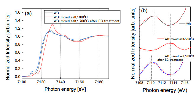
14. Wilke M, Frages F, Petit P-E, et al. (2001) Oxidation state and coordination of Fe in minerals: An Fe K-XANES spectroscopic study. Am Mineral 86: 714–730. doi: 10.2138/am-2001-5-612
    [16] 15. Westre TE, Kennepohl P, DeWitt JG, et al. (1997) A multiplet analysis of Fe K-Edge 1s → 3d pre-edge features of iron complexes. J Am Chem Soc 119: 6297–6314. doi: 10.1021/ja964352a
  • This article has been cited by:

    1. Mitsunori Honda, Yui Kaneta, Tsuyoshi Yaita, EXAFS investigation of strontium adsorption onto weathered biotite, 2023, 13, 2158-3226, 015314, 10.1063/5.0106879
  • Reader Comments
  • © 2019 the Author(s), licensee AIMS Press. This is an open access article distributed under the terms of the Creative Commons Attribution License (http://creativecommons.org/licenses/by/4.0)
通讯作者: 陈斌, bchen63@163.com
  • 1. 

    沈阳化工大学材料科学与工程学院 沈阳 110142

  1. 本站搜索
  2. 百度学术搜索
  3. 万方数据库搜索
  4. CNKI搜索

Metrics

Article views(5861) PDF downloads(2275) Cited by(1)

Figures and Tables

Figures(6)  /  Tables(1)

/

DownLoad:  Full-Size Img  PowerPoint
Return
Return

Catalog