This paper investigates the performance of the current model predictive control (CMPC) for controlling a two-stage transformerless grid-connected photovoltaic (PV) system under grid fault conditions. A maximum power point tracking (MPPT) controller was used to extract the maximum power of the PV panel. To stabilize the DC link and generate the reference current values, a proportional-integral (PI) controller was used. The CMPC strategy was implemented to control the output current of the inverter that connects the PV system to the utility grid. The system and control strategy were simulated via a MATLAB/Simulink environment. The performance of the proposed control strategy was investigated under fault conditions between the three-phase two-level inverter and the grid. Moreover, to validate the capability of the CMPC, comparative case studies were conducted between CMPC, PI, and sliding mode control (SMC) under grid fault. Case studies' results showed that under grid fault, CMPC did not introduce any overshoot or undershoot in the PV output DC current and power. However, PI and SMC produced undershoots of almost 15 kW for the output power and 45 A for the output current. Under the fault conditions, the active output power and three-phase current recovery time of the inverter was 50 ms using CMPC, compared to PI and SMC with recovery times of 80 ms and 60 ms, respectively. Moreover, a voltage dip of 75 V at the DC link voltage was recorded with CMPC under faulty conditions, while the voltage dips for PI and SMC were around 180 V.
Citation: Abdulrahman J. Babqi, NasimUllah, Ahmed Althobaiti, Hend I. Alkhammash, Asier Ibeas. Current model predictive fault-tolerant control for grid-connected photovoltaic system[J]. AIMS Energy, 2022, 10(2): 273-291. doi: 10.3934/energy.2022015
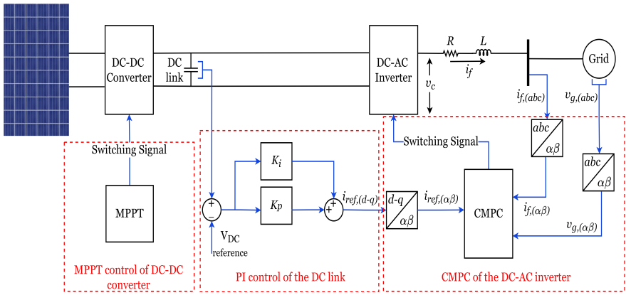
This paper investigates the performance of the current model predictive control (CMPC) for controlling a two-stage transformerless grid-connected photovoltaic (PV) system under grid fault conditions. A maximum power point tracking (MPPT) controller was used to extract the maximum power of the PV panel. To stabilize the DC link and generate the reference current values, a proportional-integral (PI) controller was used. The CMPC strategy was implemented to control the output current of the inverter that connects the PV system to the utility grid. The system and control strategy were simulated via a MATLAB/Simulink environment. The performance of the proposed control strategy was investigated under fault conditions between the three-phase two-level inverter and the grid. Moreover, to validate the capability of the CMPC, comparative case studies were conducted between CMPC, PI, and sliding mode control (SMC) under grid fault. Case studies' results showed that under grid fault, CMPC did not introduce any overshoot or undershoot in the PV output DC current and power. However, PI and SMC produced undershoots of almost 15 kW for the output power and 45 A for the output current. Under the fault conditions, the active output power and three-phase current recovery time of the inverter was 50 ms using CMPC, compared to PI and SMC with recovery times of 80 ms and 60 ms, respectively. Moreover, a voltage dip of 75 V at the DC link voltage was recorded with CMPC under faulty conditions, while the voltage dips for PI and SMC were around 180 V.

| [1] |
Owusu PA, Asumadu-Sarkodie S (2016) A review of renewable energy sources, sustainability issues and climate change mitigation. Cogent Eng 3: 1167990. https://doi.org/10.1080/23311916.2016.1167990 doi: 10.1080/23311916.2016.1167990

|
| [2] |
Hoseinzadeh S, Garcia DA (2022) Numerical analysis of thermal, fluid, and electrical performance of a photovoltaic thermal collector at new micro-channels geometry. J Energy Resour Technol 144: 062105. https://doi.org/10.1115/1.4052672 doi: 10.1115/1.4052672
|
| [3] | Hoseinzadeh S, Sohani A, Samiezadeh S, et al. (2020) Using computational fluid dynamics for different alternatives water flow path in a thermal photovoltaic (PVT) system. Int J Numer Methods Heat Fluid Flow. https://doi.org/10.1108/HFF-02-2020-0085 |
| [4] | IEA (2021) Renewables 2021, IEA, Paris. Available from : https://www.iea.org/reports/renewables-2021. |
| [5] |
Rehmani MH, Reisslein M, Rachedi A, et al. (2018) Integrating renewable energy resources into the smart grid: Recent developments in information and communication technologies. IEEE Trans Industr Inf 14: 2814–2825. https://doi.org/10.1109/TII.2018.2819169 doi: 10.1109/TII.2018.2819169
|
| [6] |
Makkiabadi M, Hoseinzadeh S, Mohammadi M, et al. (2020) Energy feasibility of hybrid PV/wind systems with electricity generation assessment under Iran environment. Appl Solar Energy 56: 517–525. https://doi.org/10.3103/S0003701X20060079 doi: 10.3103/S0003701X20060079
|
| [7] |
Al-Shetwi AQ, Hannan MA, Jern KP, et al. (2020) Power quality assessment of grid-connected PV system in compliance with the recent integration requirements. Electronics 9: 366. https://doi.org/10.3390/electronics9020366 doi: 10.3390/electronics9020366
|
| [8] | Shahid A (2018) Smart grid integration of renewable energy systems. 2018 7th International Conference on Renewable Energy Research and Applications (ICRERA), 944–948. https://doi.org/10.1109/ICRERA.2018.8566827 |
| [9] |
Zeb K, Nazir MS, Ahmad I, et al. (2021) Control of transformerless inverter-based two-stage gridconnected photovoltaic system using Adaptive-PI and adaptive sliding mode controllers. Energies 14: 2546. https://doi.org/10.3390/en14092546 doi: 10.3390/en14092546
|
| [10] |
Hoseinzadeh S, Garcia DA (2022) Numerical analysis of thermal, fluid, and electrical performance of a photovoltaic thermal collector at new micro-channels geometry. J Energy Resour Technol 144: 062105. https://doi.org/10.1115/1.4052672 doi: 10.1115/1.4052672
|
| [11] |
Hoseinzadeh S, Sohani A, Samiezadeh S, et al. (2020) Using computational fluid dynamics for different alternatives water flow path in a thermal photovoltaic (PVT) system. Int J Numer Methods Heat Fluid Flow. 31: 1618–1637. https://doi.org/10.1108/HFF-02-2020-0085 doi: 10.1108/HFF-02-2020-0085
|
| [12] |
Sohani A, Dehnavi A, Sayyaadi H, et al. (2022) The real-time dynamic multi-objective optimization of a building integrated photovoltaic thermal (BIPV/T) system enhanced by phase change materials. J Energy Storage 46: 103777. https://doi.org/10.1016/j.est.2021.103777 doi: 10.1016/j.est.2021.103777
|
| [13] |
Khodayar SH, Hoseinzadeh S, Ghadamian H, et al. (2021) Techno-economic analysis and new design of a photovoltaic power plant by a direct radiation amplification system. Sustainability 13: 11493. https://doi.org/10.3390/su132011493 doi: 10.3390/su132011493
|
| [14] | Rizzoli G, Mengoni M, Zarri L, et al. (2016) Comparison of single-phase H4, H5, H6 inverters for transformerless photovoltaic applications. IECON 2016—42nd Annual Conference of the IEEE Industrial Electronics Society, 3038–3045. https://doi.org/10.1109/IECON.2016.7792984 |
| [15] | Islam M, Hasan M, Akter P, et al. (2014) A new transformerless inverter for grid connected photovoltaic system with low leakage current. 2013 International Conference on Electrical Information and Communication Technology (EICT), 1–6. https://doi.org/10.1109/EICT.2014.6777840 |
| [16] |
Lokhande N, Phadnis G (2017) Comparison of full bridge transformerless H5, HERIC, H6 inverter topologies. Int J Innovative Res Sci Eng Technol 6: 10870–10881. https://doi.org/10.15680/IJIRSET.2017.0606136 doi: 10.15680/IJIRSET.2017.0606136
|
| [17] |
Freddy TKS, Rahim NA, Hew WP, et al. (2014) Modulation techniques to reduce leakage current in three-phase transformerless H7 photovoltaic inverter. IEEE Trans Ind Electron 62: 322–331. https://doi.org/10.1109/TIE.2014.2327585 doi: 10.1109/TIE.2014.2327585
|
| [18] |
Yilmaz U, Kircay A, Borekci S (2018) PV system fuzzy logic MPPT method and PI control as a charge controller. Renewable Sustainable Energy Rev 81: 994–1001. https://doi.org/10.1016/j.rser.2017.08.048 doi: 10.1016/j.rser.2017.08.048
|
| [19] |
Pradhan JK, Ghosh A, Bhende CN (2017) Small-signal modeling and multivariable PI control design of VSC-HVDC transmission link. Electr Power Syst Res 144: 115–126. https://doi.org/10.1016/j.epsr.2016.11.005 doi: 10.1016/j.epsr.2016.11.005
|
| [20] |
Malakondareddy B, Kumar SS, Gounden NA, et al. (2019) An adaptive PI control scheme to balance the neutral-point voltage in a solar PV fed grid connected neutral point clamped inverter. Int J Electri Power & Energy Syst 110: 318–331. https://doi.org/10.1016/j.ijepes.2019.03.012 doi: 10.1016/j.ijepes.2019.03.012
|
| [21] |
Attia H (2019) High performance PV system based on artificial neural network MPPT with PI controller for direct current water pump applications. Int J Power Electron Drive Syst 10: 1329–1338. http://doi.org/10.11591/ijpeds doi: 10.11591/ijpeds
|
| [22] |
Abo-Elyousr FK, Abdelaziz AY (2018) Optimal PI microcontroller-based realization for technical trends of single-stage single-phase grid-tied PV. Eng Sci Technol Int J 21: 945–956. https://doi.org/10.1016/j.jestch.2018.07.007 doi: 10.1016/j.jestch.2018.07.007
|
| [23] |
Khandelwal A, Nema P (2021) Application of PI controller based active filter for harmonic mitigation of grid-connected PV-system. Bulletin Electri Eng Inf 10: 2377–2383. https://doi.org/10.11591/eei.v10i5.2907 doi: 10.11591/eei.v10i5.2907
|
| [24] |
Young KD, Utkin VI, Ozguner U (1999) A control engineer's guide to sliding mode control. IEEE Trans Control Syst Technol 7: 328–342. https://doi.org/10.1109/87.761053 doi: 10.1109/87.761053
|
| [25] | Del Pizzo A, Di Noia LP, Meo S (2017) Super twisting sliding mode control of smart-inverters grid-connected for PV applications. 2017 IEEE 6th International Conference on Renewable Energy Research and Applications (ICRERA), 793–796. https://doi.org/10.1109/ICRERA.2017.8191168 |
| [26] |
Asghar M, Khattak A, Rafiq MM (2017) Comparison of integer and fractional order robust controllers for DC/DC converter feeding constant power load in a DC microgrid. Sustainable Energy Grids Networks 12: 1–9. https://doi.org/10.1016/j.segan.2017.08.003 doi: 10.1016/j.segan.2017.08.003
|
| [27] |
Ullah N, Sami I, Chowdhury MS, et al. (2020) Artificial intelligence integrated fractional order control of doubly fed induction generator-based wind energy system. IEEE Access 9: 5734–5748. https://doi.org/10.1109/ACCESS.2020.3048420 doi: 10.1109/ACCESS.2020.3048420
|
| [28] |
Ullah N, Farooq Z, Sami I, et al. (2020) Industrial grade adaptive control scheme for a micro-grid integrated dual active bridge driven battery storage system. IEEE Access 8: 210435–210451. https://doi.org/10.1109/ACCESS.2020.3039947 doi: 10.1109/ACCESS.2020.3039947
|
| [29] |
Sami I, Ullah S, Ali Z, et al. (2020) A super twisting fractional order terminal sliding mode control for DFIG-based wind energy conversion system. Energies 13: 2158. https://doi.org/10.3390/en13092158 doi: 10.3390/en13092158
|
| [30] | Babqi AJ, Yi Z, Shi D, et al. (2018) Model predictive control of H5 inverter for transformerless PV systems with maximum power point tracking and leakage current reduction. IECON 2018—44th Annual Conference of the IEEE Industrial Electronics Society, 1860–1865. https://doi.org/10.1109/IECON.2018.8591386 |
| [31] |
Ma M, Liu X, Lee KY (2020) Maximum power point tracking and voltage regulation of two-stage grid-tied PV syst based model predict control. Energies 13: 1304. https://doi.org/10.3390/en13061304 doi: 10.3390/en13061304
|
| [32] |
Metry M, Balog RS (2020) An adaptive model predictive controller for current sensorless MPPT in PV systems. IEEE Open J Power Electron 1: 445–455. https://doi.org/10.1109/OJPEL.2020.3026775 doi: 10.1109/OJPEL.2020.3026775
|
| [33] |
Zhao Y, An A, Xu Y, et al. (2021) Model predictive control of grid-connected PV power generation system considering optimal MPPT control of PV modules. Prot Control Mod Power Syst 6: 1–12. https://doi.org/10.1186/s41601-021-00210-1 doi: 10.1186/s41601-021-00210-1
|
| [34] |
Liu J, Cheng S, Liu Y, et al. (2019) FCS-MPC for a single-phase two-stage grid-connected PV inverter. IET Power Electron 12: 915–922. https://doi.org/10.1049/iet-pel.2018.5676 doi: 10.1049/iet-pel.2018.5676
|
| [35] | Ullah N, Sami I, Jamal BA, et al. (2021) Processor in the loop verification of fault tolerant control for a three phase inverter in grid connected PV system. Energy Sources 1–17. https://doi.org/10.1080/15567036.2021.2015486 |
| [36] |
Xia C, Liu T, Shi T, et al. (2013) A simplified finite-control-set model-predictive control for power converters. IEEE Trans Ind Inf 10: 991–1002. https://doi.org/10.1109/TII.2013.2284558 doi: 10.1109/TII.2013.2284558
|
| [37] |
Kouro S, Cortés P, Vargas R, et al. (2008) Model predictive control—A simple and powerful method to control power converters. IEEE Trans Ind Electron 56: 1826–1838. https://doi.org/10.1109/TIE.2008.2008349 doi: 10.1109/TIE.2008.2008349
|
| [38] | Rodriguez J, Cortes P (2012) Predictive control of power converters and electrical drives. John Wiley & Sons, Ltd. https://doi.org/10.1002/9781119941446 |


Figures(16) / Tables(2)

Abdulrahman J. Babqi, NasimUllah, Ahmed Althobaiti, Hend I. Alkhammash, Asier Ibeas. Current model predictive fault-tolerant control for grid-connected photovoltaic system[J]. AIMS Energy, 2022, 10(2): 273-291. doi: 10.3934/energy.2022015


 DownLoad: