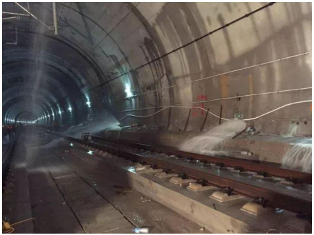
The striking dominance of groundwater-related defects in the operational high-speed railway tunnels in China calls for swift and accurate detection and identification. Thus, it is a new attempt to detect the water-bearing defects at 5 to 10 meters via train-borne transient electromagnetic method in operating tunnels. Due to the short detection distance, the interaction between transmitting and receiving coils is more important than those normally used coils. Thus, numerical and experimental methods are combined to investigate the mutual induction. The influence of turns, current and coil size on the mutual induction and the impact of damping coefficient on the receiving system are manifested. To further verify these findings, full-scale model experiments are conducted. During these physical experiments, the detection results of different coil parameters including coil size, number of turns, and emission current are compared and analyzed. Then, a special effort to minimize the induction between transmitting and receiving coils is expended to acquire the suitable coils for close range detection in the tunnel context. Finally, in order to verify the availability of the detection system, different detection distances are conducted. It turns out that different detection distances have slight difference at the detection results, but they are still within the measuring range of the detection instrument. Obviously, these findings can provide theoretical support for the detection of water-bearing anomalies in operating tunnels and it also has reference significance for the detection of anomalies at close distance.
Citation: Zongyang Li, Taiyue Qi, Shaojie Qin, Wangping Qian. The research on minimizing the induction between the transmitting and receiving coils in close range transient electromagnetic inspection of groundwater-related defects in the operating tunnels[J]. Mathematical Biosciences and Engineering, 2021, 18(4): 4508-4527. doi: 10.3934/mbe.2021229
The striking dominance of groundwater-related defects in the operational high-speed railway tunnels in China calls for swift and accurate detection and identification. Thus, it is a new attempt to detect the water-bearing defects at 5 to 10 meters via train-borne transient electromagnetic method in operating tunnels. Due to the short detection distance, the interaction between transmitting and receiving coils is more important than those normally used coils. Thus, numerical and experimental methods are combined to investigate the mutual induction. The influence of turns, current and coil size on the mutual induction and the impact of damping coefficient on the receiving system are manifested. To further verify these findings, full-scale model experiments are conducted. During these physical experiments, the detection results of different coil parameters including coil size, number of turns, and emission current are compared and analyzed. Then, a special effort to minimize the induction between transmitting and receiving coils is expended to acquire the suitable coils for close range detection in the tunnel context. Finally, in order to verify the availability of the detection system, different detection distances are conducted. It turns out that different detection distances have slight difference at the detection results, but they are still within the measuring range of the detection instrument. Obviously, these findings can provide theoretical support for the detection of water-bearing anomalies in operating tunnels and it also has reference significance for the detection of anomalies at close distance.

| [1] | C. X. Liu, Cause Analysis and construction technology study of water-leakage of liner in Huangdengxian Tunnel, J. Railw. Sci. Eng., 2 (2010), 79-82. |
| [2] | P. Li, Displacement characteristics of high-speed railway tunnel construction in loess ground by using multi-step excavation method, Tunn. Undergr. Sp. Tech., 51 (2015), 41-55. |
| [3] |
X. Liang, T. Qi, Z. Jin, W. Qian, Hybrid support vector machine optimization model for inversion of tunnel transient electromagnetic method, Math. Biosci. Eng., 17 (2020), 3998-4017. doi: 10.3934/mbe.2020221

|
| [4] | K. Y. Wang, H.Xiao, Y. J. Shang, K. M. Sun, W. T. He, Prediction of rock burst at wall rocks of tunnels in Southwest, J. Eng. Geol., 5 (2014), 903-914. |
| [5] |
G. Q. Xue, C. Y. Bai, S. Yan, S. Greenhalgh, M. F. Li, N. N. Zhou, Deep sounding tem investigation method based on a modified fixed central-loop system, J. Appl. Geophys., 76 (2012), 23-32. doi: 10.1016/j.jappgeo.2011.10.007
|
| [6] |
G.Q. Xue, L. Zhang, N. Zhou, W. Chen, Developments measurements of TEM sounding in china, Geol. J., 55 (2020), 1636-1643. doi: 10.1002/gj.3544
|
| [7] | E. Auken, Approaching 10 microsec (and earlier) with the Skytem system, ASEG Extended Abstracts, 1 (2010), 1. |
| [8] | B. R. Spies, The dual loop configuration of the transient electromagnetic method, Geophysics, 40 (1974), 1051. |
| [9] | G. Q. Xue, J. L. Cheng, N. N. Zhou, W. Y. Chen, H. Li, Detection and monitoring of water-filled voids using transient electromagnetic method: A case study in shanxi, china, Environ. Earth Sci., 70 (2013), 2263-2270. |
| [10] |
A. E. Plotnikov, Evaluation of limitations of the transient electromagnetic method in shallow-depth studies: Numerical experiment, Russ. Geol. Geophys., 55 (2014), 907-914. doi: 10.1016/j.rgg.2014.06.009
|
| [11] | Z. Xi, X. Long, L. Huang, S. Zhou, G. Song, H. Hou, et al., Opposing-coils transient electromagnetic method focused near-surface resolution, Geophysics, 81 (2016), E279-E285. |
| [12] |
D. V. Fitterman, W. L. Anderson, Effect of transmitter turn-off time on transient soundings, Geoexploration, 24 (1987), 131-146. doi: 10.1016/0016-7142(87)90087-1
|
| [13] | F. Kamenetsky, C. Oelsner, Distortions of EM transients in coincident loops at short time-delays, Geophys. Prospect., 48 (2008), 983-993. |
| [14] |
I. M. Lee, Q. H. Truong, D. H. Kim, J. S. Lee, Discontinuity detection ahead of a tunnel face utilizing ultrasonic reflection: Laboratory scale application, Tunn. Undergr. Sp. Tech., 24 (2009), 155-163. doi: 10.1016/j.tust.2008.06.001
|
| [15] | Denghai Bai, Maxwell Meju, The effect of two types of turn-off current on TEM responses and the correction techniques, Seismology and Geology, 23 (2001), 245-251. |
| [16] | B. R. Spies, D. E. Eggers, The use and misuse of apparent resistivity in electromagnetic methods, Geophysics, 51 (1986), 1462. |
| [17] |
K. Vozoff, Electromagnetic methods in applied geophysics, Geophys. Surveys, 4 (1980), 9-29. doi: 10.1007/BF01452955
|
| [18] | H. J. Wang, Characteristics of damping coefficient effect on transient electromagnetic signal, Chin. J. Geophys., 53 (2010), 428-434. (In Chinese). |


Figures(24)

Zongyang Li, Taiyue Qi, Shaojie Qin, Wangping Qian. The research on minimizing the induction between the transmitting and receiving coils in close range transient electromagnetic inspection of groundwater-related defects in the operating tunnels[J]. Mathematical Biosciences and Engineering, 2021, 18(4): 4508-4527. doi: 10.3934/mbe.2021229


 DownLoad: