Research article Special Issues

The influence of a non-aligned semi-elliptical surface crack on a quarter-circle corner crack in an infinitely large plate under uniaxial tension

  • Received: 23 September 2016 Accepted: 31 October 2016 Published: 08 November 2016
  • Fitness-for-Service codes require the evaluation of non-aligned multiple cracks in various practical applications. For on-site inspection, decision needs to be made on whether the cracks should be treated as coalesced or separate multiple cracks in case of non-aligned parallel cracks,. In the existing literature, criteria and standards for the adjustment of multiple nonaligned cracks are very source dependent, and those criteria and standards are often derived from on-site service experience without rigorous and systematic verification. Based on this observation, the authors previously reported on the effect between an edge and an embedded parallel crack in 2-D scenarios and, more recently, in 3-D scenarios of circular cracks. Since realistic crack configurations detected using non-destructive methods are generally 3-D in nature, the study of 3-D effect of non-aligned cracks with different shapes is deemed necessary in order to obtain more practical guidance in the usage of rules speculated in Fitness-for-Service codes. In this study, the effect of a semi-elliptic surface crack on a quarter-circle corner crack in an infinitely large plate under uniaxial tension was investigated. To keep this study more focused, the size of the quarter-circle corner crack was kept constant. A detailed analysis was then given to the crack shape effect of the embedded semi-elliptic cracks on the fixed quarter-circle corner crack. The analysis is repeated for various combinations of separation distances S and H between the two cracks. The results from this study are collectively significant to the understanding of the correlation between the criteria and standards in Fitness-for-Service community and the consequence of their usage in engineering practice.

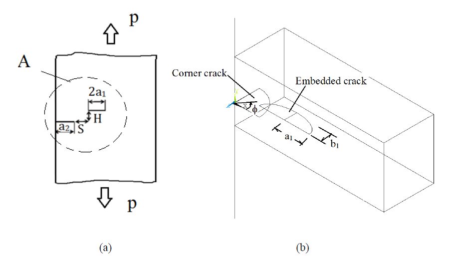
    Citation: Mordechai Perl, Qin Ma, Cesar Levy. The influence of a non-aligned semi-elliptical surface crack on a quarter-circle corner crack in an infinitely large plate under uniaxial tension[J]. AIMS Materials Science, 2016, 3(4): 1474-1492. doi: 10.3934/matersci.2016.4.1474

    Related Papers:

    [1] Kisaburo Azuma, Yinsheng Li . Interaction factors for two elliptical embedded cracks with a wide range of aspect ratios. AIMS Materials Science, 2017, 4(2): 328-339. doi: 10.3934/matersci.2017.2.328
    [2] R.R.Bhargava, Kamlesh Jangid, Pavitra Tripathi . A Mode-III strip saturation model for two collinear semi-permeable cracks in a piezoelectric media. AIMS Materials Science, 2016, 3(4): 1507-1519. doi: 10.3934/matersci.2016.4.1507
    [3] N. Akhtar, S. Hasan . Assessment of the interaction between three collinear unequal straight cracks with unified yield zones. AIMS Materials Science, 2017, 4(2): 302-316. doi: 10.3934/matersci.2017.2.302
    [4] Bohdan Stasyuk . Interacting cracks 3D analysis using boundary integral equation method. AIMS Materials Science, 2016, 3(4): 1796-1810. doi: 10.3934/matersci.2016.4.1796
    [5] A.-V. Phan . Dynamic stress intensity factor analysis of the interaction between multiple impact-loaded cracks in infinite domains. AIMS Materials Science, 2016, 3(4): 1683-1695. doi: 10.3934/matersci.2016.4.1683
    [6] R. Citarella, M. Lepore, M. Perrella, C. Calì . Multiple crack propagation by DBEM in a riveted lap-joint. AIMS Materials Science, 2016, 3(4): 1577-1586. doi: 10.3934/matersci.2016.4.1577
    [7] Mordechai Perl, Tomer Saley . The cumulative detrimental impact of pressure and autofrettage on the fatigue life of an externally cracked modern tank gun barrel. AIMS Materials Science, 2019, 6(5): 833-851. doi: 10.3934/matersci.2019.5.833
    [8] Genshichiro Katsumata, Valéry Lacroix, Yinsheng Li . Effect of interaction of embedded crack and free surface on remaining fatigue life. AIMS Materials Science, 2016, 3(4): 1748-1758. doi: 10.3934/matersci.2016.4.1748
    [9] Pierre Dulieu, Valéry Lacroix . Mutual interaction of stress concentration and stress intensity factor between semi-circular notch and crack. AIMS Materials Science, 2016, 3(4): 1520-1533. doi: 10.3934/matersci.2016.4.1520
    [10] Michael A. Stamps, Jeffrey W. Eischen, Hsiao-Ying Shadow Huang . Particle- and crack-size dependency of lithium-ion battery materials LiFePO4. AIMS Materials Science, 2016, 3(1): 190-203. doi: 10.3934/matersci.2016.1.190
  • Fitness-for-Service codes require the evaluation of non-aligned multiple cracks in various practical applications. For on-site inspection, decision needs to be made on whether the cracks should be treated as coalesced or separate multiple cracks in case of non-aligned parallel cracks,. In the existing literature, criteria and standards for the adjustment of multiple nonaligned cracks are very source dependent, and those criteria and standards are often derived from on-site service experience without rigorous and systematic verification. Based on this observation, the authors previously reported on the effect between an edge and an embedded parallel crack in 2-D scenarios and, more recently, in 3-D scenarios of circular cracks. Since realistic crack configurations detected using non-destructive methods are generally 3-D in nature, the study of 3-D effect of non-aligned cracks with different shapes is deemed necessary in order to obtain more practical guidance in the usage of rules speculated in Fitness-for-Service codes. In this study, the effect of a semi-elliptic surface crack on a quarter-circle corner crack in an infinitely large plate under uniaxial tension was investigated. To keep this study more focused, the size of the quarter-circle corner crack was kept constant. A detailed analysis was then given to the crack shape effect of the embedded semi-elliptic cracks on the fixed quarter-circle corner crack. The analysis is repeated for various combinations of separation distances S and H between the two cracks. The results from this study are collectively significant to the understanding of the correlation between the criteria and standards in Fitness-for-Service community and the consequence of their usage in engineering practice.


    Nomenclature

    a1half semi-elliptical crack length
    b1semi-elliptical crack depth
    a2edge crack length
    Hvertical crack separation distance
    Shorizontal crack separation distance
    EYoung’s modulus
    KImode I SIF
    KImaxmaximum mode I SIF of the quarter-circle corner crack
    K0Normalizing SIF
    papplied tensile load
    υPoisson’s ratio
    σyyield stress
    φparametric angle


    1. Introduction

    The degradation process of plant components, especially in the case of stress corrosion cracking (SCC) and fatigue [1,2], makes the study of multiple cracks significantly important. Based on fracture mechanics concepts, structural integrity of cracked components can be evaluated in conjunction with Fitness-for-Service standards.

    If the multiple cracks lie on the same cross-sectional plane, they are considered aligned cracks. If the multiple cracks lie on parallel planes, then they are considered to be non-aligned parallel cracks. The latter case requires crack alignment rules. Several crack alignment rules exist that can be considered for in-service evaluations. The existing crack alignment rules include those found in the American Society of Mechanical Engineers Boiler and Pressure Vessel Code Section XI (ASME Section XI) [3], Guide to Methods for Assessing the Acceptability of Flaws in Metallic Structures [4], European Fitness-for-Service Network (FITNET) [5], American Petroleum Institute (API) 579-1/ASME FFS-1 [6], or Rules on Fitness-for-Service for Nuclear Power Plant Components in the Japan Society of Mechanical Engineers (JSME, S NA1-2008) [7]. These rules differ from each other and some alignment rules may provide overly conservative results while others give non-conservative assessments.

    The effect of multiple non-aligned cracks has been studied in case of two offset parallel cracks contained in a large steel plate in recent years. For instance, Kamaya [8] studied the growth evaluation of multiple interacting surface cracks by combination of numerical methods and experimental studies. Hasegawa et al. [9] studied the effect of two parallel embedded non-aligned flaws for Fitness-for-Service based on the principle of linear elastic fracture mechanics (LEFM). In their most recent studies Hasegawa et al. [10,11], Miyazaki et al. [12], and Suga et al. [13,14] considered plastic collapse behavior for dissimilar non-aligned cracks. However, none of these existing studies addressed the crack interaction behavior between two offset parallel cracks with one of them an edge or corner crack.

    A recent study by Ma et al. [15] addressed the issue of an embedded crack interacting with an edge crack based on 2-D analysis. Only recently a first attempt was made to three-dimensionally analyze the effect between a surface semi-circular crack and a quarter-circle corner crack by Ma et al. [16]. It is, therefore, the purpose of the present paper to extend this 3-D analysis and to investigate the effect a surface semi-elliptical crack on a non-aligned quarter-circle corner crack on the fracture behavior of an infinitely large solid under uniaxial tension. The stress intensity factors (SIFs) along the crack front of the quarter-circle corner crack are studied for various geometrical configurations. The variation of the geometrical configuration includes the crack ellipticity b1/a1=0.1 ~1, and the relative crack size of the two parallel cracks a1/a2=1/3 ~2 in addition to other parametric combinations such as the normalized gap, H/a2=0.4 ~2, and the normalized separation distance, S/a2=−0.5 ~2 (see Figure 1), between cracks on parallel planes.

    Figure 1. (a) A Front view of the entire plate including parameter definitions of the geometrical relationship of the two interacting non-aligned cracks, a quarter circle corner crack and a semi-elliptical crack. (b) Local view of the quarter circle corner crack in relation to the semi-elliptical crack.

    The designations used herein are the same as those in the recent study by Ma et al. [15]. The analysis results show that the 3-D SIFs along the crack front of the quarter-circle corner crack are significantly affected by the elliptic configuration of the surface crack in addition to other parametric quantities. However, the conclusions drawn are similar to those of the recent 2-D analysis [15] and the 3-D analysis [16]. That is, certain existing standards/criteria provide results that are much more conservative than others while certain ones do not provide adequate information for application.


    2. Finite Element Modeling


    2.1. Solid Modeling

    Figure 1 depicts an infinitely long plate or solid under uniaxial tension containing a quarter-circle corner crack and a semi-elliptical surface crack on parallel planes both perpendicular to the load. The plate is assumed to be made of steel with Young’s modulus E=200 GPa, Poisson’s ratio υ=0.3, and yield stress σy= 304 MPa. The remote tensile load is equivalent to a nominal tensile stress applied to the model and is taken as p= 2 KPa. The remote tensile load is applied onto the top surface of the plate while the bottom surface of the plate is fixed.

    For all cases, the plate is considered elastic and infinitely long in size. The width of the plate is W and its depth D. The cracks are always assumed to be perpendicular to the load applied. Furthermore, the quarter-circle corner crack has a crack radius a2, and the semi-elliptical surface crack has a half-length a1 and a depth b1 (Figure 1b). The horizontal gap between the cracks is S and the vertical separation distance is H as shown in Figure 1a.


    2.2. Finite Element Idealization

    The model is solved using the standard FE code ANSYS [17]. A global mesh [16] of the entire plate is generated using 10-node tetrahedron elements (SOLID92). The 10-node tetrahedron element has a quadratic displacement behavior and is well suited to model irregular meshes specifically for a plate with quarter-circle corner crack and a semi-elliptical surface crack. The elements are varied in size, small near the cracks and gradually increased when moving away from them.

    The SIFs are solved using the submodeling technique adopted in the previous work by Ma [18], and Levy et al. [19,20]. This submodel is a toroid-like submodel of a full crack model with a quarter-circle crack configuration. Generally speaking, the submodel is constructed by 20-node isoparametric solid brick elements (SOLID95) and made of three layers containing the two crack surfaces, which are created with a small opening from the deepest line of the crack surface [18]. The first layer of elements consists of 160 20-node isoparametric elements that are collapsed to form the wedges to accommodate the singularity at the crack front. On top of this layer, are two additional layers consisting of 20-node, isoparametric elements. The sub-model consists of a total of 6543 degrees of freedom enabling the accurate evaluation of the SIF distribution along the crack front at intervals of 9 deg. from for φ=0 to 90 deg. The radial length of the sub-model is 2*a2/3 for the quarter-circle crack. A detailed description of the finite element modeling and the evaluation of the SIFs is described in references [18,19,20].

    Convergence tests were performed using the stress intensity factor as the convergence criterion. In brief, based on the trial and error methodology, it is anticipated, for most cases, that the level of error was approximately less than 5% for meshes having more than 200, 000 DOFs, about half of them being assigned to the small volume. Typical meshes for the coarse model included about 50, 000 elements with approximately 60, 000 nodes. The option always chosen was the one whereby the software automatically adjusted element shapes and aspect ratios for all meshes.


    3. Results and Discussion

    The effect of the surface crack on the corner crack was found to depend on multiple factors including the normalized separation space between the two cracks in the horizontal direction S/a2, the normalized separation distance in the vertical direction H/a2 and the relative crack size a1/a2 as well as the crack geometrical configurations. In this study, the corner quarter-circular crack is kept at a certain size, and the surface crack’s non-circularity effect on overall performance is evaluated. The SIF is normalized with K0=1.12p(pa2)1/2, the stress intensity factor of a 2-D crack emanating from the free surface in a half space.


    3.1. The Effect of Interaction of Similar Size Cracks on the SIFs

    In this section, cases when the quarter-circle corner crack and the semi-elliptical surface crack are identical in size are evaluated, i.e., a1=a2, while varying the ellipticity of the surface crack such that b1/a1=0.1-1.0. Two types of plots are presented. One is the distribution of the normalized SIFs along the quarter-circle corner crack front when affected by the surface crack, while varying its ellipticity and keeping the separation distances fixed. The other type of plot is the normalized maximum SIFs for the quarter-circle corner crack as a function of the normalized horizontal separation distance, S/a2, and the surface crack ellipticity, b1/a1, for certain fixed normalized vertical separation distance, H/a2. Both types clearly demonstrate the significant influence of crack geometrical configuration and space relationship on the interaction behavior of the two parallel cracks.

    Figure 2 is provided as an illustration to describe the normalized SIF distribution along the crack front for the quarter-circle corner crack of size a2=15 mm, interacting with a semi-elliptic surface crack of size a1=15 mm, of varying crack depth b1. The vertical separation distance H/a2=0.4 is constant and the relative crack size is a1/a2=1. The normalized horizontal separation distance is taken as S/a2=−0.5. One may see that the effect of the surface crack geometry on the SIFs can be dramatic. For all surface crack ellipticities b1/a1, SIFs along the crack front of the corner quarter-circular crack decrease to a minimum value and then increase, but not significantly, to reach another but lower maximum value at φ=90°. At any point along the crack front, the shallower the surface crack, the smaller is its effect on the SIF. The most critical location for these cases is at φ=0°, which is the location of the corner crack tip that is nearest to the surface crack.

    Figure 2. The normalized SIF distribution along the crack front for a quarter-circle corner crack affected by a semi-elliptic surface crack (a2=a1=15 mm, H/a2=0.4, and S/a2=−0.5).

    As discussion proceeds, we will see that this is not always the case. The specific location where the maximum SIF occurs along the crack front depends on the specific geometrical configuration. The maximum SIF value may occur at either φ=0° or φ=90° along the corner crack front. The SIF behavior along the quarter-circle corner crack front is controlled by the specific parametric combinations, i.e., the relative crack size of the two parallel cracks, the crack ellipticity of the surface crack and the separation distances.

    The effect of shallow semi-elliptical cracks on the corner crack (when b1/a1 is small) is significantly different from its effect of deep cracks (when b1/a1 is close to 1). For example, when b1/a1=0.1, which is the shallowest semi-elliptical crack presented herein, the SIF for the corner crack is only ~2% higher at φ=0° than at φ=90°. However, when b1/a1=1, which is the deepest semi-elliptical crack considered, the SIF for the corner crack is ~64% higher at φ=0°than at φ=90°. The effect of the ellipticity of the semi-elliptical crack is considerably different for various points along the front of the corner crack, e.g., at φ=0°, the SIF increases by up to ~77% when the crack ellipticity increases from 0.1 to 1 while at φ=90°, the SIF increases by up to ~9% only.

    Figure 3 shows a plot similar to Figure 2 except that in the present case the cracks are horizontally farther apart with a separation distance of S/a2=0.5. It is evident that the effect of one crack on the other is greatly diminished as the horizontal separation distance S/a2 becomes much larger. As ellipticity is increased from 0.1 to 1.0, the effect of the semi-elliptical crack on the corner crack in the present case results in an increase of the SIFs of up to ~10% at φ=0° and of just up to ~1.5% at φ=90°, while in the previous case (Figure 2) it was ~77% and ~9% respectively. As the horizontal distance S/a2 is further increased the influence of the ellipticity of the embedded crack on the corner crack continues to diminish until all the curves collapse into one which indicates that the two cracks no longer “feel” the existence of each other.

    Figure 3. The normalized SIF distribution along the crack front for a quarter-circle corner crack affected by a semi-elliptic surface crack for H/a2=0.4 (a2=a1=15 mm) and S/a2=0.5.

    Figure 4 shows a plot similar to Figure 2 except that in the present case the cracks are vertically farther apart with an separation distance of H/a2=0.8. It is clear that the effect of one crack on the other is greatly diminished as the vertical separation distance H/a2 becomes larger. When ellipticity is increased from 0.1 to 1.0, the effect of the semi-elliptical crack on the corner crack in this case results in a decrease of up to ~25% at φ=0°while in the case of Figure 2 it resulted in an increase of up to ~77%. At φ=90°, the SIF value increases by up to ~12% in the present case while it increased by up to ~9% in the previous case. Again, as the vertical separation distance increases, the influence of the embedded crack’s ellipticity on the corner crack becomes smaller and smaller.

    Figure 4. The normalized SIF distribution along the crack front for a quarter-circle edge corner crack affected by a semi-elliptic surface crack for H/a2=0.8 (a2=a1=15 mm) and S/a2=−0.5.

    By comparison, the graphical trends shown in Figure 4 are very different from those shown in Figure 2. Namely, at φ=0° the effect is reversed, i.e., the SIF magnitude decreases with increasing ellipticity b1/a1. At the same time, the maximum SIF values occur at φ=90° instead of at φ=0°. Apparently, there is a location where the SIF value is the same for all b1/a1. That is to say, there exists a certain φ value at which the ellipticity plays no role on the magnitude of the SIFs. We may refer to this location as the crossover location. This crossover location moves quickly towards the end φ=0° with the increase of the horizontal separation distance, S/a2.

    Attention is directed to similar cases when a1=a2=10 mm (not shown here). The results for these cases manifest the same type of relationships as in the previous cases when a1=a2=15 mm between the two cracks.

    The behavior of the maximum SIF, KImax, is of great interest in this study. Maxima may occur at either 0 or 90 degree along the crack front and are different from case to case. Figure 5 shows the maximum normalized SIFs versus the normalized horizontal separation space S/a2 as a function of b1/a1 for the quarter-circle corner crack-semi-elliptic surface crack combination while other parameters are fixed; namely, H/a2=0.4, a2=15 mm, a1/a2=1.

    Figure 5. The maximum normalized SIFs vs. S/a2 for a quarter-circle corner crack affected by a semi-elliptic surface crack H/a2=0.4, (a2=a1=15 mm).

    The normalized maximum SIFs, KImax/K0, decrease as the elliptic crack becomes shallower. Apparently, the worst crack configuration shown in this figure is when two parallel cracks “overlap” (S/a2 < 0). The normalized maximum SIFs decrease significantly and monotonically as the horizontal separation distance S/a2 increases from the “overlapping”range starting at S/a2=−0.5. This decreasing trend of the maximum SIFs continues until it reaches approximately the value of the corner crack in an semi-infinite body, i.e., the semi-elliptical crack has no more influence on the corner crack for horizontal separation distances exceeding S/a2≥1. In this case, the crack configuration is no longer important and can be treated as two separate cracks for Fitness-for-Service considerations.

    The crack depth effect, S/a2, is complicated by the combination of other geometrical quantities. To illustrate this concept, look at the case of S/a2=−0.5, which is the worst overlapping case, where the maximum SIF value increases by ~77% when the ellipticity of the surface crack b1/a1 changes from the shallowest case of b1/a1=0.1 to the deepest case of b1/a1=1. However, if we then take a closer look at the case of S/a2=0.5, which is slightly away from overlapping, then the maximum SIF value drops by only ~10% when the ellipticity of the surface crack b1/a1 changes from the deepest case to the shallowest case. Yet, as S/a2 moves a little further to 1, the maximum SIF value drops by only ~4%. This discussion demonstrates the significant effect of the combined parameters on the maximum SIFs. In summary, when the two parallel cracks are severely overlapped, the effect of the surface crack ellipticity is much more pronounced. However, when the horizontal distance S/a2 becomes larger, the effect of the surface crack ellipticity on the maximum SIFs is very much diminished.

    From another point of view, the above argument may be enhanced if we take a closer look at a certain fixed ellipticity. For example, at b1/a1=1, the deepest crack, the maximum normalized SIFs decrease by ~39% from S/a2=−0.5 to S/a2=0.5. However, the maximum SIFs decrease only about 8% for the rest of the separation cases from S/a2=0.5 to S/a2=2. This demonstrates clearly that with the increase of horizontal separation, S/a2, the surface crack ellipticity becomes much less influential on the maximum SIFs. At the same time, if b1/a1=0.1 case is scrutinized, the maximum normalized SIFs decrease by only ~1.5% from S/a2=−0.5 to S/a2=0.5. The maximum SIFs further decrease by only about 0.2% for the rest of the separation cases from S/a2=0.5 to S/a2=2. This indicates that the SIF become insensitive to the surface crack ellipticity as the horizontal separation distance increases when the ellipticity is sufficiently small.

    Figure 6 represents the maximum normalized SIF distribution as a function of the horizontal separation distance, S/a2, as the vertical separation distance is further increased to H/a2=0.8 from H/a2=0.4 in Figure 5. As the vertical separation becomes larger, the surface crack ellipticity effect on the SIFs is diminished overall. For example, in the worst overlapping case of S/a2=−0.5, the maximum SIF value increases by only ~12% (Figure 6) as compared ~77% (Figure 5) when the ellipticity of the surface crack b1/a1 increases from 0.1 to 1.

    Figure 6. The maximum normalized SIFs vs. S/a2 for a quarter-circle edge corner crack affected by a semi-elliptic surface crack for H/a2=0.8 (a2=a1=15 mm).

    3.2. The Effect of Interaction of Dissimilar Size Long Cracks on their SIFs

    In this section, cases when the surface crack size is much larger than the quarter-circle corner crack size are discussed. Specifically, discussion focuses on the cases when a2=15 mm & a1=30 mm and a1/a2=2. Two types of plots analogous to those shown in the previous section are presented. Although the counterpart plots may be similar in trends, the difference between the SIF magnitudes can be dramatic. This indicates that the significance of the size dissimilarity between the surface crack and the quarter-circle corner crack on the SIFs cannot be overlooked.

    Figure 7 is the counter plot to Figure 2 for a1/a2=2. While keeping other parameters the same, the surface crack size is doubled. One may see that the overall trend of the plot is similar with that in Figure 2. However, while the effect on shallow cracks (when b1/a1 is small) seems not significantly affected by the size change, the increase of the SIF magnitudes for deep cracks (when b1/a1 is close to 1) is greatly pronounced. For example, when b1/a1=0.1, which is the shallowest case among all the cases presented herein, the SIF value is about 5% higher at φ=0° than at φ=90°. This is comparable to 2% increase for the identical case of b1/a1=0.1 in Figure 2. However, when b1/a1=1, which is the deepest crack case evaluated here, the SIF value is about 111% higher at φ=0° than at φ=90°, which indicates that the increase of the SIF magnitude is much more dramatic than what is shown in Figure 2 where the increase was about 64% for the case of b1/a1=1.

    Figure 7. The normalized SIF distribution along the crack front for a quarter-circle edge corner crack affected by a semi-elliptic surface crack for H/a2=0.4 (a2=15 mm & a1=30 mm) and S/a2=−0.5.

    At the same time, a closer look at the same crack front location shows that at φ=0°, the SIF value increases by ~167% when the crack ellipticity increases from 0.1 to 1. For Figure 2 the increase was only ~77% at φ=0°. At φ=90°, the SIF value increases ~33%, which is indeed a more significant increase compared to the increase of ~9% shown on Figure 2 at φ=90°.

    Figure 8 is the counter plot to Figure 3. The parameters of the two figures are the same except a1/a2=2 in Figure 8. We see that the surface crack’s effect on the corner crack remains relatively strong in comparison with those of Figure 3. For example, at φ=0°, the SIF value increases ~27% when the crack ellipticity increases from 0.1 to 1, which is three times as large as the results for the same ellipticity increase shown in Figure 3 at φ=0°. In the meantime, at φ=90°, the SIF value only increases ~5%, which is slightly higher than ~1.5% shown in Figure 3 at φ=90°.

    Figure 8. The normalized SIF distribution along the crack front for a quarter-circle edge corner crack affected by a semi-elliptic surface crack for H/a2=0.4 (a2=15mm & a1=30mm) and S/a2=0.5.

    Figure 9 changes the absolute value of the vertical separation distance from 6 mm to 12 mm and it is the counter plot to Figure 4. The normalized vertical separation distance is H/a2=0.8 and a1/a2=2 keeping S/a2 unchanged. While similar trends are observed for the two parallel cracks from these two plots, the crack size effects on the SIF values are apparently pronounced in Figure 9. For example, considering the crack front location at φ=90°, where the maximum SIF occurs, the SIF value increases ~42% when the crack ellipticity increases from 0.1 to 1. This increase is 3.5 times higher than the ~12% maximum SIF increase found for Figure 4.

    Figure 9. The normalized SIF distribution along the crack front for a quarter-circle edge corner crack affected by a semi-elliptic surface crack for H/a2=0.8 (a2=15 mm & a1=30 mm) and S/a2=−0.5.

    At the same time, it is observed that a crossover location exists along the crack front for all b1/a1. For the cases presented herein, we see that this crossover point moves from case to case. In Figure 9, crossover is around 25° whereas in Figure 4 crossover was near 40-45°. Also, for larger crack size, the SIFs at φ=90° are more dramatically affected than at φ=0°.

    Figure 10 is the counter plot to Figure 5, which demonstrates the interaction behavior of the maximum SIFs as a function of the normalized horizontal separation space S/a2 and as a function of the surface crack ellipticity b1/a1. However, for this case, the surface crack is doubled in length, i.e., a2=15 mm, a1=30 mm, or a1/a2=2, compared to Figure 5 where a1/a2=1.

    Figure 10. The maximum normalized SIFs vs. S/a2 for a quarter-circle edge corner crack affected by a semi-elliptic surface crack for H/a2=0.4 (a2=15 mm & a1=30 mm).

    For all cases herein, we again see that the normalized maximum SIFs, KImax/K0, drop significantly and monotonically as the horizontal separation space S/a2 increases from the overlapping range starting at S/a2=−0.5. The decreasing trend largely depends on the surface crack ellipticity or depth. While the maximum SIFs are not much affected by the horizontal separation distance S/a2 for very shallow cracks such as when b1/a1=0.1, the maximum SIFs are dramatically affected by the horizontal separation distance for deep surface cracks. For deep surface cracks, the maximum SIFs drop the most between S/a2=−0.5 ~0.5.

    To illustrate the significance of the crack size effect for this case, let’s take a closer look at the case of S/a2=−0.5, which is the worst overlapping case. The maximum SIF value drops ~167% when the ellipticity of the surface crack changes from the deepest case of b1/a1=1 to 0.1. This decrease is much more dramatic than the decrease of ~77% shown in Figure 5. If we then take yet another close look at the case of S/a2=0.5, which is slightly away from crack overlapping situation, then the maximum SIF value drops by ~27% when the ellipticity of the surface crack changes from the deepest case of b1/a1=1 to 0.1. This is again much more than the ~10% increase at the same location on its counter plot. By viewing a fixed ellipticity value, for example b1/a1=1, the deepest crack situation, and comparing the maximum normalized SIFs from S/a2=−0.5 to S/a2=0.5, a decrease of ~54% is noted. This is again a much more significant decrease than ~39% for the same situation shown in Figure 5. For the rest of the separation cases from S/a2=0.5 to S/a2=2 and for the same ellipticity value, the maximum SIFs decrease by ~18% in this figure in comparison with an 8% decrease found in Figure 5. This demonstrates that the maximum SIFs are affected much more dramatically by the horizontal separation distance for longer and deeper surface cracks than for the shorter and shallower ones.

    It is not surprising that we have the same conclusion for very shallow cracks such that the SIFs become insensitive with the increase of the horizontal separation distance when the surface crack ellipticity is sufficiently small.

    Figure 11 is the counter plot to Figure 6. This figure again shows how the maximum normalized SIF distribution behaves as a function of the horizontal separation distance S/a2 for each fixed crack ellipticity b1/a1. But the vertical separation distance between the two parallel cracks is now set to be H/a2=0.8 and here a1/a2=2. It is noted that the vertical separation distance plays an important role in the influence of the semi-elliptical surface crack on the corner crack. However, this impact of both horizontal and vertical is much more dramatic for longer and deeper cracks than for shorter and shallower cracks as mentioned previously. For example, at the case of S/a2=−0.5, which is the worst overlapping case, the maximum SIF value increases by ~42% when the ellipticity of the surface crack b1/a1 changes from 0.1 to 1. This is much more than the ~12% increase shown in its counter plot.

    Figure 11. The maximum normalized SIFs vs. S/a2 for a quarter-circle edge corner crack affected by a semi-elliptic surface crack for H/a2=0.8 (a2=15 mm & a1=30 mm).

    3.3. The Effect of Interaction of Dissimilar Size Short Cracks on their SIFs

    In this section, cases when the surface crack size is smaller or much smaller than the quarter-circle corner crack size are investigated. Specifically, discussion is focused on the cases when a2=15 mm and a1=10 mm as well as when a1=5 mm.

    Figure 12 is the counter plot to Figure 2 for a1/a2=2/3. While keeping other parameters the same, the surface crack size is reduced to a1=10 mm. One may see that the overall trend of the plots again bear similarity to those found in Figure 2. However, while the effect of shallow cracks (when b1/a1 is small) on the quarter-circle corner crack seems not significantly affected by the size change, the decrease of the SIF magnitudes of deep cracks (when b1/a1 is close to 1) is again apparent. For example, when b1/a1=0.1, the shallowest case evaluated here, the SIF value is about 1% higher at φ=0° than at φ=90°, which is comparable to 2% for the identical case of b1/a1=0.1 in Figure 2. However, when b1/a1=1, the deepest crack case, the SIF value is about 37% higher at φ=0°than at φ=90°, which indicates that the increase of the SIF magnitude is much less than the increase of 64% shown in Figure 2 for the identical case. However, if the crack is even smaller, e.g., at a1=5 mm, then the SIF value is only 5% higher at φ=0° than at φ=90° for the deepest crack case of b1/a1=1.

    Figure 12. The normalized SIF distribution along the crack front for a quarter-circle edge corner crack affected by a semi-elliptic surface crack for H/a2=0.4 (a2=15 mm & a1=10 mm) and S/a2=−0.5.

    When evaluating the SIFs at the same crack front location, in this case, at φ=0°, the SIF value increases ~40% when the crack ellipticity increases from 0.1 to 1. This is compared to an increase of ~77% in the values shown on Figure 2 at the same crack front location. But this increase is only 5% at the same crack front location for the case where a1=5 mm.

    Figure 13 is the counter plot to Figure 3. The results are based on a different horizontal separation distance S/a2=0.5, the same as in Figure 3. It is noted that ellipticity effect on the SIFs becomes insignificant for this case. For example, at φ=0°, the SIF value increases only ~4% when the surface crack ellipticity increases from 0.1 to 1, which is much smaller than ~10% shown on its counter plot, Figure 3, at φ=0°. If the case of a1=5 mm is considered, the insignificance of the ellipticity effect becomes even more apparent.

    Figure 13. The normalized SIF distribution along the crack front for a quarter-circle edge corner crack affected by a semi-elliptic surface crack for H/a2=0.4 (a2=15 mm & a1=10 mm) and S/a2=0.5.

    Figure 14 has as its counter plot Figure 4. This plot is based on the vertical separation distance H/a2=0.8, the same as in Figure 4. While similar trends are observed for the effect of the semi-elliptic surface crack on the quarter-circle crack, when the crack size becomes small, the ellipticity effects become less pronounced. For example, considering the crack front location at f=90°, where the maximum SIFs occur, the SIF value increases ~4% when the crack ellipticity increases from 0.1 to 1. This increase is much less than ~12% shown in Figure 4. Also, the plot crossovers are nearly at the same angular location.

    Figure 14. The normalized SIF distribution along the crack front for a quarter-circle edge corner crack affected by a semi-elliptic surface crack for H/a2=0.8 (a2=15 mm & a1=10 mm) and S/a2=−0.5.

    Figure 15 has as its counter plot Figure 5, which demonstrates the interaction behavior of the maximum SIFs as a function of the normalized horizontal separation space, S/a2 and as a function of the surface crack ellipticity, b1/a1. The vertical separation distance H/a2 is the same; however, for this case, the surface crack is shorter in length than in its counter plot, i.e., a2=15 mm, a1=10 mm versus a2=15 mm, a1=15 mm in Figure 5.

    Figure 15. The maximum normalized SIFs vs. S/a2 for a quarter-circle edge corner crack affected by a semi-elliptic surface crack for H/a2=0.4 (a2=15 mm & a1=10 mm).

    For all cases shown, it is noted that the normalized maximum SIFs, KImax/K0, drop significantly and monotonically as the horizontal separation range increases from the overlapping range value of S/a2=−0.5 to a large separation value of 2. The decreasing trend largely depends on the surface crack ellipticity or depth. While the maximum SIFs are not much affected by the horizontal separation distance S/a2 for very shallow cracks such as when b1/a1=0.1, the maximum SIFs are dramatically affected by the horizontal separation distance for deep surface cracks. For deep surface cracks, the maximum SIFs drop again the most between S/a2=−0.5 ~0.5.

    To illustrate the significance of the surface crack size effect for this case, look at the case of S/a2=−0.5, which is the worst overlapping case. At this S/a2 value the maximum SIF value drops ~40% when the ellipticity of the surface crack b1/a1 changes from b1/a1=1 to 0.1. This decrease is much less than the decrease of ~77% shown on its counter plot, Figure 5, where the surface crack is 1.5 times as long. While another close look at the case of S/a2=0.5, which is slightly away from the overlapping situation, yields that the maximum SIF value drops only ~5% when the ellipticity of the surface crack changes from b1/a1=1 to 0.1. This is again much less than ~10% shown at the same location on its counter plot, Figure 5, for the longer surface crack.

    If a certain fixed ellipticity is scrutinized, for example, at b1/a1=1, the deepest surface crack, the maximum normalized SIFs decrease ~25% from S/a2=−0.5 to S/a2=0.5. This is much less than ~39% for the same situation shown on its counter plot. For the rest of the separation cases from S/a2=0.5 to S/a2=2, the maximum SIFs decrease ~4% in comparison with an 8% decrease shown on the counter plot Figure 5. This demonstrates again that the maximum SIFs are affected much more dramatically by the horizontal separation distance for longer and deeper surface cracks than for the shorter and shallower ones.

    It is not surprising that the same conclusion is drawn for very shallow cracks that the horizontal separation has little effect on the SIFs when the surface crack ellipticity is sufficiently small.


    3.4. The Influence of Flaw Alignment Rules

    Figure 16 shows the same 3-D results of Figure 5 but with the criteria included from two different Fitness-for-Service sources [4,5] considering 2-D as well 3-D configurations. The thick dashed curve illustrates the effect of the British Standards flaw alignment rules (BritS) [4] while the thick dotted-dashed curve illustrates the effect of the flaw alignment rules imposed by FITNET [5]. The corresponding light dashed curve and the light dotted-dashed curve represent the corresponding 2-D results.

    Figure 16. Normalized max SIFs vs. S/a2 as a function of H/a2 for a quarter-circle corner crack (a2=15 mm; a1=15 mm) with FITNETstandard and BritS standard superposed.

    The BritS criterion is given as

    S1a1+a2 (1)

    where S1 is the distance connecting the two closest crack tips of the corner crack and the surface crack.

    The FITNET criterion is given as

    Hmin(2a1,a2) (2)

    The BritS apparently considers the effect of separation parameters of both relative vertical distance, H/a2, and the relative horizontal distance, S/a2, as well as the relative crack size, a1/a2, in an implicit manner. The thick dashed curve was obtained considering the following relationship from the criterion by (1):

    Ha2(a1a2+1)2(Sa2)2 (3)

    Therefore, based on the BritS, each point on the thick dashed curve corresponds to a different value of vertical separation distance H/a2. The criterion reflects the influence of all the relative parameters of S/a2, H/a2 and a1/a2. But the FITNET does not include any effect from the horizontal separation dimension, S/a2, which is an important parameter that influences the SIF values, as shown from our previous discussions. In fact, for the case presented in Figure 16, the min (2a1, a2) is a2=15 mm, and thus H/a2=1. Thus the thick dotted-dashed curve was obtained under a constant relative separation distance, H/a2, in the same manner as that for other cases under constant H/a2 values.

    The two criteria apparently provide very different scenarios for the judgment of alignment vs. non-alignment for two parallel offset cracks, which is the same as observed from the recent 2-D analysis results [15]. For certain crack separation conditions, one criterion may consider the same two cracks on parallel planes to act as one while the other criterion will suggest that the cracks should be considered as separate ones. The critical values from the BritS and the FITNETrules as demonstrated in Figure 16 clearly show that the FITNET will provide a much higher barrier for the cracks to be judged as aligned ones. Thus the BritS is a much more conservative rule, and it provides much lower critical values of the SIFs, i.e., conservative results in Fitness-for-Service applications.

    For the sake of comparison, the critical SIFs from 2-D analysis are included on the graph, as well. Apparently 2-D analysis results provide extremely conservative information regarding when the two parallel cracks shall be considered as aligned ones.

    The results from other standards [3,6,7], though not presented in this paper, are perceived to bear the same behavior in the same manner as discussed here.


    4. Conclusions

    In this study, the effect of a semi-elliptic surface crack on a quarter-circle corner crack in an infinitely large plate under uniaxial tension was investigated and the SIF along the crack front of a quarter-circle corner crack is evaluated as a function of the embedded surface crack geometry, the vertical and horizontal separation distances between the cracks, as well as the relative crack sizes of the two cracks.

    It is found that the maximum stress intensity factor of the corner crack KImax is enhanced by the presence of the embedded semi-elliptical crack, thus making it more critical. The increase in KImax is highly dependent on four parameters, i.e., as the horizontal (S) and the vertical (H) separation distances decrease, and as the relative size of the semi-elliptical crack (a1/a2) and its ellipticity (b1/a1) increase, KImax becomes larger by up to about 170% in the cases treated herein (viz., S/a2=−0.5, H/a2=0.4, a1/a2=2, and b1/a1=1). As the separation distances increase and as the semi-elliptical crack size and ellipticity decrease this effect diminishes to the point of becoming practically non-existent, signifying “no effect” of the semi-elliptical crack on the corner crack.

    The present 3-D results also show that the surface crack depth has a profound effect on the SIFs of the corner crack while keeping other parameters unchanged. Because the crack ratios are constant and the ellipticity is varied, this is equivalent to a surface crack depth variation. Further, a crossover point is found whereby the SIF is the same at the same φ value. That crossover point tends to φ=0°as the surface crack ellipticity becomes less than 1. While small ellipticity plays insignificant role on the SIFs, the effect on the SIFs due to deep surface cracks can be dramatic. The overall effect leads to the conclusion that existing alignment rules used to evaluate the “fitness for service” do not agree and can lead to opposite conclusions.


    Acknowledgements

    This work used the Extreme Science and Engineering Discovery Environment (grant number PSC Grant MSS140004P). The second author (QM) acknowledges the support from his University through a Faculty Development Grant. We acknowledge that this work was essentially presented at the 2016 ASME PVP Conference in Vancouver, BC, Canada and gratefully thank ASME for allowing the paper to be published in this special issue of the AIMS publication.


    Conflict of Interest

    All authors declare no conflicts of interest in this paper.


    [1] Okamura Y, Sakashita A, Fukuda T, et al. (2003) Latest SCC issues of core shroud and recirculation piping in Japanese BWRs. Transactions of the 17th International Conference on Structural Mechanics in Reactor Technology (SMIRT 17), Prague, Czech Republic, WG01-1.
    [2] Kamaya M, Haruna T (2006) Crack Initiation Model for Type 304 Stainless Steel in High Temperature Water. Corros Sci 48: 2442–56. doi: 10.1016/j.corsci.2005.09.015
    [3] ASME (2007) B&PV Code Section XI.
    [4] British Standards (2005) BritS 7910.
    [5] European Fitness-for-Service Network (FITNET), GTC1-2001-43049.
    [6] American Petroleum Institute (2007) Fitness-for-Service. API 579-1/ASME FFS-1.
    [7] The Japan Society of Mechanical Engineers (2008) Rules on Fitness-for-Service for Nuclear Power Plant. JSME S NA1-2008 (in Japanese).
    [8] Kamaya M (2008) Growth evaluation of multiple interacting surface cracks. Part I: Experiments and simulation of coalesced crack. Eng Fract Mech 75: 1350–1366.
    [9] Hasegawa K, Saito K, Miyazaki K (2009) Alignment Rule for Non-Aligned Flaws for Fitness-for Service Evaluations Based on LEFM. ASME JPVT 131: 041403.
    [10] Hasegawa K, Miyazaki K, Saito K (2010) Behavior of plastic collapse moments for pipes with two non-aligned flaws. ASME 2010 Pressure Vessels and Piping Division/K-PVP Conference, Bellevue, Washington, USA.
    [11] Hasegawa K, Miyazaki K, Saito K (2011) Plastic collapse loads for flat plates with dissimilar Non-aligned through-wall cracks. ASME 2011 Pressure Vessels and Piping Conference, Baltimore, Maryland, USA.
    [12] Miyazaki K, Hasegawa K, Saito K (2011) Effect of flaw dimensions on ductile fracture behavior of non-aligned multiple flaws in a plate. ASME 2011 Pressure Vessels and Piping Conference, Baltimore, Maryland, USA.
    [13] Suga K, Miyazaki K, Kawasaki S (2011) Study on the interaction of multiple flaws in ductile fracture process. ASME 2011 Pressure Vessels and Piping Conference, Baltimore, Maryland, USA.
    [14] Suga K, Miyazaki K, Senda R, et al. (2011) Ductile fracture simulation of multiple surface flaws. ASME 2011 Pressure Vessels and Piping Conference, Baltimore, Maryland, USA.
    [15] Ma Q, Levy C, Perl M (2013) A LEFM Based Study on the Interaction between an Edge and an Embedded Parallel Crack. ASME 2013 Pressure Vessels and Piping Conference, Paris, France.
    [16] Ma Q, Levy C, Perl M (2015) 3-D Interaction of a Corner Flaw with a Non-Aligned Surface Flaw in an Infinitely Large Plate under Tension. Procedia Eng 130: 711–730. doi: 10.1016/j.proeng.2015.12.172
    [17] Swanson Analysis System Inc. (2009) ANSYS 12 User Manual.
    [18] Ma Q (1999) Stress Concentration and Stress Intensity Factors of a Multi-eroded, Cracked Autofrettaged Pressurized Thick-Walled Cylinder. Master’s thesis, FIU.
    [19] Levy C, Perl M, Ma Q (2001) The Influence of Multiple Axial Erosions on a Three-Dimensional Crack in Determining the Fatigue Life of Autofrettaged Pressurized Cylinders. ASME JPVT 124: 1–6.
    [20] Levy C, Perl M, Kokkavessis N (1996) Three-Dimensional Interaction Effects in an Internally Multicracked Pressurized Thick-Walled Cylinder. Part II—Longitudinal Coplanar Crack Arrays. ASME JPVT 118: 364–368.
  • Reader Comments
  • © 2016 the Author(s), licensee AIMS Press. This is an open access article distributed under the terms of the Creative Commons Attribution License (http://creativecommons.org/licenses/by/4.0)
通讯作者: 陈斌, bchen63@163.com
  • 1. 

    沈阳化工大学材料科学与工程学院 沈阳 110142

  1. 本站搜索
  2. 百度学术搜索
  3. 万方数据库搜索
  4. CNKI搜索

Metrics

Article views(4892) PDF downloads(934) Cited by(0)

Article outline

Other Articles By Authors

/

DownLoad:  Full-Size Img  PowerPoint
Return
Return

Catalog