Research article

Parametric study of a diffuser for horizontal axis wind turbine power augmentation

  • Received: 20 September 2019 Accepted: 12 November 2019 Published: 29 November 2019
  • For a wider dissemination and implementation of small wind turbines for rural electrification in developing countries, the cost of the system must be reduced. When searching for systems that are efficient and economical, Diffuser Augmented Wind turbine seems to have a potential role by increasing the power output and reducing the cost of the system most importantly at low speeds. In this paper, a detailed study has been done on Diffuser Augmented Wind Turbines to find a parametric relationship for power augmentation for horizontal axis wind turbines. A suitable diffuser was selected and its parameters were identified and their relationships were formulated based on Computational Fluid Dynamics. The result has been validated using experimental analysis. Based on the result, the power output and performance of a wind turbine is improved while using diffuser. The result shows the velocity peaks at a location immediately after the diffuser inlet. The velocity, then, levels off and further decreases as the flow continues to the diffuser outlet and exits it. This suggests a possible location of a wind turbine at the vicinity of the inlet. Based on the result, the length of the diffuser and the flange height were the major parameters to be considered. Maximum velocity ratios up to 1.5 were obtained with potential power increase of more than 2 times. It has also been observed that velocity ratios of up to 1.3 can be achieved with more compact diffusers potentially reducing the cost of the diffuser and the whole system. The mathematical relations obtained for the major parameters and the velocity ratio can be used in the performance prediction and optimization of a diffuser. Finally, possible directions for further research are recommended considering that this work shows a good agreement with previous works and predictions.

    Citation: Nathnael Bekele, Wondwossen Bogale. Parametric study of a diffuser for horizontal axis wind turbine power augmentation[J]. AIMS Energy, 2019, 7(6): 841-856. doi: 10.3934/energy.2019.6.841

    Related Papers:

    [1] Azevedo Joaquim, Mendonça Fábio . Small scale wind energy harvesting with maximum power tracking. AIMS Energy, 2015, 2(3): 297-315. doi: 10.3934/energy.2015.3.297
    [2] Nour Khlaifat, Ali Altaee, John Zhou, Yuhan Huang . A review of the key sensitive parameters on the aerodynamic performance of a horizontal wind turbine using Computational Fluid Dynamics modelling. AIMS Energy, 2020, 8(3): 493-524. doi: 10.3934/energy.2020.3.493
    [3] Hassam Nasarullah Chaudhry, John Kaiser Calautit, Ben Richard Hughes . The Influence of Structural Morphology on the Efficiency of Building Integrated Wind Turbines (BIWT). AIMS Energy, 2014, 2(3): 219-236. doi: 10.3934/energy.2014.3.219
    [4] Sri Kurniati, Sudirman Syam, Arifin Sanusi . Numerical investigation and improvement of the aerodynamic performance of a modified elliptical-bladed Savonius-style wind turbine. AIMS Energy, 2023, 11(6): 1211-1230. doi: 10.3934/energy.2023055
    [5] Nadwan Majeed Ali, Handri Ammari . Design of a hybrid wind-solar street lighting system to power LED lights on highway poles. AIMS Energy, 2022, 10(2): 177-190. doi: 10.3934/energy.2022010
    [6] Ammar E. Ali, Nicholas C. Libardi, Sohel Anwar, Afshin Izadian . Design of a compressed air energy storage system for hydrostatic wind turbines. AIMS Energy, 2018, 6(2): 229-244. doi: 10.3934/energy.2018.2.229
    [7] Rashid Al Badwawi, Mohammad Abusara, Tapas Mallick . Speed control of synchronous machine by changing duty cycle of DC/DC buck converter. AIMS Energy, 2015, 3(4): 728-739. doi: 10.3934/energy.2015.4.728
    [8] Ayman B. Attya, T. Hartkopf . Wind Turbines Support Techniques during Frequency Drops — Energy Utilization Comparison. AIMS Energy, 2014, 2(3): 260-275. doi: 10.3934/energy.2014.3.260
    [9] Sunimerjit Kaur, Yadwinder Singh Brar, Jaspreet Singh Dhillon . Multi-objective real-time integrated solar-wind-thermal power dispatch by using meta-heuristic technique. AIMS Energy, 2022, 10(4): 943-971. doi: 10.3934/energy.2022043
    [10] Salih Nawaf Akour, Mahmoud Azmi Abo Mhaisen . Parametric design analysis of elliptical shroud profile. AIMS Energy, 2021, 9(6): 1147-1169. doi: 10.3934/energy.2021053
  • For a wider dissemination and implementation of small wind turbines for rural electrification in developing countries, the cost of the system must be reduced. When searching for systems that are efficient and economical, Diffuser Augmented Wind turbine seems to have a potential role by increasing the power output and reducing the cost of the system most importantly at low speeds. In this paper, a detailed study has been done on Diffuser Augmented Wind Turbines to find a parametric relationship for power augmentation for horizontal axis wind turbines. A suitable diffuser was selected and its parameters were identified and their relationships were formulated based on Computational Fluid Dynamics. The result has been validated using experimental analysis. Based on the result, the power output and performance of a wind turbine is improved while using diffuser. The result shows the velocity peaks at a location immediately after the diffuser inlet. The velocity, then, levels off and further decreases as the flow continues to the diffuser outlet and exits it. This suggests a possible location of a wind turbine at the vicinity of the inlet. Based on the result, the length of the diffuser and the flange height were the major parameters to be considered. Maximum velocity ratios up to 1.5 were obtained with potential power increase of more than 2 times. It has also been observed that velocity ratios of up to 1.3 can be achieved with more compact diffusers potentially reducing the cost of the diffuser and the whole system. The mathematical relations obtained for the major parameters and the velocity ratio can be used in the performance prediction and optimization of a diffuser. Finally, possible directions for further research are recommended considering that this work shows a good agreement with previous works and predictions.


    More than 71% of the population of Ethiopia is living without electricity and rural electrification rate of Ethiopia is less than 10% [1]. Ethiopia has wind energy potential of 10 GW. However, the installed capacity is 324 MW (Ashegoda Wind Farm, 120 MW, Adama Wind Farm Ⅰ, 51 MW and Adama Wind Farm Ⅱ, 153 MW). This implies the country uses only 3.24% of its potential [2,3]. Therefore, the country has 96.76% untapped wind energy potential. However, more than 82% population of Ethiopia lives in rural areas and the rural electrification rates is less than 10% [4]. Thus, finding a solution for rural electrification that is efficient and economical in Ethiopia is very important. Besides, all the installed wind turbines are large turbines that are connected to the grid. This is due to the fact that the efficiency of larger wind turbines is higher and they have more economic efficiency [5]. Major technological advancements in the development of large-scale wind turbines have been done. However, small wind turbines used for rural and urban area applications are somewhat under research [6]. Small scale wind turbine for rural application has several challenges; such as low wind speed, variable wind direction and high turbulence intensity [7,8].

    Several researches have been done on improving performance of small wind turbines for rural area applications and on reducing cost of electricity generation. Diffuser Augmented Wind Turbine (DAWT) is an innovative approach under investigation since 1975 to improve the life cycle economics of wind energy conversion and to improve performance since more wind power can be extracted than conventional rotors of the same diameter at the same free wind speed [9,10,11]. Different researchers highlighted the benefits Augmented Wind Turbines [12,13,14,15,16,17,18]. Kosasih and Hudin studied the performance of a small wind turbine without diffuser and diffuser-augmented micro wind turbine models subjected to different levels of turbulence. Based on their research, the diffuser increases the power coefficient CP by a factor of almost two [19]. Lubitz and Shomer highlighted the importance of examining the benefits of a diffuser with respect to the additional cost and complexity of the system [20].

    Kesby, Bradney and Clausen concluded that DAWTs are suited for energy production in an urban environment than a traditional HAWT [21]. Based on their research, they concluded that the Levelised Cost of Energy of a small wind turbine could be significantly reduced making them more attractive to the consumer if 3D printing technology is used to manufacture the turbine blades and diffuser. Jafari and Kosasih performed a computational fluid dynamics (CFD) study and based on their research power augmentation is strongly dependent on the geometry of the diffuser, such as length and ratio of the diffuser outlet area to rotor area [10]. The higher ratio of the diffuser outlet area to rotor area, the lower the exit pressure, and the higher the mass flow rate [10,17].

    The power available in the wind has a cubic relationship with the wind speed. Thus, any acceleration of the wind right before the wind rotor will have a considerably large impact on the generated power. Researches and developments have led to the use of flow concentration devices used to locally accelerate the wind. These devices are one of the options for improving the performance of wind turbines. Nozzles, cylindrical ducts and diffusers or a combination of these can be used. One of the advantages of these devices is the reduction of tip losses. Nozzles and diffusers increase the mass flow rate into the rotor plane. However, the optimum design of these devices should be identified for an economically viable design. This calls for identifying the major parameters and their relationships with performance.

    Diffuser Augmented Wind Turbines (DAWTs) have been researched for quite a long period of time [22,23,24,25,26,27]. DAWTs 'inhale' the oncoming wind by creating low pressure immediately behind the diffuser. The focus on DAWTs has been important because they have considerable amount of power augmentation. This allows them to function in low wind speed regions. They are not also significantly affected by fluctuations in wind speeds and the wind direction. In addition, many researchers claim that the power coefficient can be improved. Other advantages include reduced tip losses and noise, and better safety [21,22,28].

    For a cost-effective and less costly venture into harnessing wind energy, small wind turbine systems can be used for rural electrification. Though small wind systems are less costly, the cost of energy (COE) is still high. Sivasegaram analytically examined the influence of size of duct augmented wind turbines on cost effectiveness and concluded that the ratio of cost to weight changes inversely with the sixth power of diameter and that cost to power ratio will fall sharply with diameter, making larger systems more economical [25]. If more energy can be produced for the same developed system and cost, the COE can be reduced. The major energy extraction component of a wind turbine is the rotor. The energy extracted depends on the rotor area and aerodynamic performance of the rotor blades. However, the major variable is the wind speed at the rotor plane. Thus, the larger wind speed going through the rotor area, the larger the power production will be.

    Nevertheless, the systems developed in this regard have not been much successful. However, the use of devices to increase the mass flow rate through the rotor blades has been proven feasible through many researches. This study focuses on conducting a research on performance improvement of small wind turbine using computational fluids dynamics (CFD) and experimental analysis. It involves identifying the important parameters in diffuser designs and their relationship with velocity increase and, thus, augmentation in power. It focuses on the parametric relationships of a diffuser for a small, horizontal axis wind turbine. The output of the research result will range from being an input for commercial product development endeavors to an input for other researches on performance improvement of small wind turbine for rural electrification.

    Fluid flow problems can be solved analytically using CFD technique. CFD can be a useful tool if it is carefully modeled and interpreted. Here, ANSYS Fluent, one of the most common CFD tools, is used to model and analyze the different diffusers. The different models incorporated different values for the parameters. As discussed in the literature review, the following are the major parameters: Diffuser area ratio (β) or opening angle (α), Diffuser length or width (L), Flange height (H) and Flange angle (α). Diffuser area ratio (β) is the ratio of the diffuser outlet area with the diffuser inlet area. It can also be represented by the opening angle, which can be calculated using the diffuser inlet and outlet radius (or diameter) with the diffuser length. The diffuser used for this analysis is as shown in Figures 1.1 and 1.2.

    Figure 11.  Diffuser parameters.
    Figure 12.  Major parameters (Sectional view).

    The area ratio and the opening angle are mathematically presented as follows;

    β=AreaoutletAreainlet (1)
    α=atan(xL), where x=DoD2 (2)

    The diffuser length (L) is the central axis distance between the diffuser inlet and outlet. It is normalized by the diffuser inlet diameter (D) for convenience. Accordingly, the remaining length parameters are normalized by the diffuser inlet diameter (D). The area ratio or the opening angle can be used to define the outlet diameter. Consequently, there is no need to define two diameters. Therefore, the diffuser length-to-inlet diameter ratio will be LD and the flange height to inlet diameter ratio will be HD.

    The diffuser length and flange height were used in the simulation. The opening angle was excluded from the analysis because its effects were negligible for small angles (0°–6°). The flange angle was not also included in the analysis because the researcher believes that the parameter should be studied after a complete parametric analysis. This is validated in that only one researcher considered the flange angle [29].

    The flange height has been included in the major parameters because various researchers have obtained results that flanges improved the diffuser performance by generating turbulence immediately behind the diffuser [29,30,31,32,33]. Since flow separation occurs in the diffuser due to adverse pressure gradient, the low pressure created at the diffuser outlet helps the flow to remain attached to the diffuser wall.

    For simplicity, the dimensionless forms of these parameters are used. This allows for few changes in the simulation. Both parameters are normalized by the diffuser inlet diameter. The dependent parameter in this study is the acceleration factor (or the velocity ratio). This is the local velocity normalized by the free stream velocity, (UU) is referred to velocity ratio hereafter.

    Though a curved diffuser interior surface is found to be advantageous as observed in the research conducted by [30,34], this model does not include such a feature for ease of manufacturing. In addition, the interior surface is not in the scope of this study. Based on this, the remaining parameters can be set. The clearance between the tipoff the rotor blade and the diffuser is taken to be 0.01 m based on [30]. Hence, the inlet diameter will be D = 0.2 m. The parameters used for the validation model is shown in Table 1.

    Table 1.  Parameters for the validation model.
    No Parameters Value Dimensions
    1 Area ratio (Opening angle: 4°) -
    2 L/D 1.5 L = 0.3 m
    3 H/D 0.5 H = 0.1 m

     | Show Table
    DownLoad: CSV

    Two-dimensional analysis was used to reduce computation resource and time. This method is used by various researchers [29,33,35] and found to be useful and acceptably accurate. Furthermore, the Spalart-Allmaras turbulence model is used for the CFD solver [33]. In addition, from Mansour's work, Spalart-Allmaras is a good model for turbulence [32]. Second order upwind scheme was set. Convergence criteria of 0.0001 was sued for all parameters. The model was validated based on the experiment by [31]. The on-axis velocity ratio distribution is shown in Figure 1.3.

    Figure 13.  On-axis velocity ratio distribution.

    The current model underestimates the velocity increase and over-predicts the lowering of the pressure. Since the work majorly involves the velocity distribution, the author believes that the model can be used. The general trends of the velocity and pressure distribution are observed to follow the trend of the experimental work. The velocity distribution obtained has a maximum error percentage of 8%.

    Table 2 shows the mesh statistics. The quality of the mesh is very important for the quality of CFD results. A finer mesh will give a more accurate result. Furthermore, the results will converge more rapidly. However, a finer mesh also means longer computational time and higher cost. There is need to balance between accuracy and cost (and/or time). "The standard method to test for grid independency is to increase the resolution and repeat the simulation" and check if the results have an appreciable difference [36]. In line with this, a mesh independence test was conducted based on a validation model. The following results were obtained and the final mesh was selected. The grid independence test and mesh details are shown Figure 1.4 and 1.5 respectively.

    Table 2.  Mesh statistics.
    Model Mesh Statistics (Number of nodes) Mesh Size Mesh Refinement Used
    1 2281 Fine None
    2 3016 Fine 2
    3 3016 Fine 3

     | Show Table
    DownLoad: CSV
    Figure 14.  Grid independence test.
    Figure 15.  Mesh details.

    Mesh refinement was used on the diffuser surface and at the symmetry axis to provide a finer and more accurate velocity distribution. The two-dimensional and axisymmetric model of the diffuser and the computational domain was modelled in SOLIDWORKS 2017 and exported as an IGES model. The computational model used for validation was developed based on Owisa' work [37] and shown in Figure 1.6.

    Figure 16.  Computational domain.

    The inlet lip has an advantageous effect as observed by Mansour and Ohya [31,32]. However, the length of the inlet lip is important in actually defining its effect. For long lengths, it will have a disadvantage in that it will act as a nozzle and the flow avoids it [30]. The inlet lip is not included due to this fact. Since the analysis is wind flow, the inlet boundary condition can be modelled as a uniform flow with the outlet boundary condition as a pressure outlet. A symmetry boundary condition will be used for the lower boundary along the axis of symmetry and the upper boundary. The diffuser surfaces are considered as walls and, thus, the no-slip condition holds. This agrees with other researchers' work [29,37]. The current computational domain used for our analysis is presented in Figure 1.7. The summary of the boundary conditions used for this analysis is shown Table 3.

    Figure 17.  Computational domain.
    Table 3.  Summary of boundary conditions.
    Boundary Condition Type
    Inlet Inlet Velocity: 5 m/s
    Outlet Pressure Outlet
    Diffuser Wall Wall: No-slip

     | Show Table
    DownLoad: CSV

    The CFD results have to be validated through experiment. Due to the unavailability of a suitable wind tunnel and measurement instruments, an existing airflow bench was modified for a 2D experimental setup. The diffuser was modelled with specific geometric parameters and made to match the simulation Re number. The arrangement in airflow bench is shown in Figure 1.8.

    Figure 18.  Arrangement in airflow bench.

    The airflow bench used is a product of TecQuipment made for education purpose. The flow visualization module was modified for this experiment. The 2D model was designed to fit this module. The model was 3D printed and was attached to a customized board. It is an exact representation of the CFD model.

    The length of the diffuser and the flange heights were varied for different simulations. The on-axis velocity was extracted from the results as shown in Figure 1.9, in an attempt to quantify the effect of the diffuser on the velocity field. In general, a similar trend was observed for the different diffuser, where the velocity increased as the flow approached the diffuser. The following velocity ratios were obtained from the simulations. For a no-flange configuration, the velocity distribution along the central axis was obtained to be as follows.

    Figure 19.  On-axis velocity distribution for diffuser without flange configuration and L/D range between 0.1 and 1 (left) and between 1.1 and 2 (right).

    In the LD range of 0.1 to 2, there was a direct relationship between the maximum velocity ratio and LD. As the value of LD increases, the velocity ratio increases. In order to develop the relationship between the velocity ratio and LD, the maximum velocity ratio along the central axis is selected. This is because that value is unique in comparison to other values. Therefore, the maximum velocity ratio is plotted with LD as shown in Figure 1.10.

    Figure 110.  Max velocity ratio Vs L/D (without flange).

    For a no-flange configuration, a maximum on-axis velocity ratio of about 1.325 was achieved for the maximum length-to-diameter ratio for this study. This velocity corresponds to a velocity of 6.625 m/s. However, the maximum velocity along the central axis does not represent the maximum velocity inside the diffuser. Figure 1.11 shows that the velocity also varies along the radial position from the central axis. The velocity increases with increasing radial position until it becomes maximum and diminished due to no-slip condition at the diffuser wall. The maximum velocity for LD=2, is about 6.82 m/s near the diffuser wall. The velocity increase is the highest at the diffuser inlet region. As the length-to-diameter ratio increases the 'increased velocity' region expands to the central region of the diffuser. The 'increased velocity' region decreases in size as the flow progresses to the outlet.

    Figure 111.  Velocity contours showing radial velocity variation for no-flange configuration (left: with L/D = 0.3 right: L/D = 1).

    For a diffuser with flange configuration, the flange height-to-diameter ratio was evaluated for values of 0.1 and 0.2. The following central axis velocity distribution was obtained for a flange height-to-diameter ratio of 0.1 as shown in Figure 1.12.

    Figure 112.  On-axis velocity distribution for diffuser with flange configuration and L/D range between 0.1 and 1 (left) and between 1.1 and 2 (right).

    For a with-flange configuration of HD=0.1, as shown in Figure 1.13, a maximum on-axis velocity ratio of about 1.45 was achieved for the L/D ratio of 2, the maximum for this study. This velocity corresponds to a velocity of 7.25 m/s. However, as discussed earlier, the actual maximum velocity inside the diffuser is found further away from the central axis along the radial position and has a value of 7.59 m/s near the diffuser wall as shown in Figure 1.14.

    Figure 113.  Maximum on-axis velocity ratio Vs L/D (H/D = 0.1).
    Figure 114.  Velocity contour for a flanged diffuser (H/D = 0.1).

    The velocity contour shows that the maximum velocity inside the diffuser can reach up to 6.3 m/s. This represents a value greater than those achieved by a diffuser without flange. Figure 1.15 shows the on-axis velocity distribution for diffuser with flange configuration.

    Figure 115.  On-axis velocity distribution for diffuser with flange configuration and L/D range between 0.1 and 1 (left) and between 1.1 and 2 (right).

    For a with- flange configuration of HD=0.2, a maximum on-axis velocity ratio of about 1.51 was achieved for the L/D ratio of 2, the maximum for this study, is depicted as shown in Figure 1.16 and the velocity contour for a flanged diffuser of HD=0.2 is shown in Figure 1.17. This velocity corresponds to a velocity of 7.55 m/s. However, as discussed earlier, the actual maximum velocity inside the diffuser is found further away from the central axis along the radial position and has a value of 7.69 m/s near the diffuser wall.

    Figure 116.  Max velocity ratio Vs L/D (H/D = 0.2).
    Figure 117.  Velocity contour for a flanged diffuser (H/D = 0.2).

    With the flanged configuration of H/D = 0.2, the velocities that are achieved in the diffuser are values with maximum of 6.55 m/s, showing an improvement on the previous flanged configuration of H/D = 0.1. The maximum on-axis velocity increased as a flange was added and the flange height increased. By the addition of a diffuser to the flow field, the on-axis wind speed increased from 5 m/s to 6.625 m/s forLD=2. This is a 32.5% increase. In summary, the increments are depicted as shown in Table 4.

    Table 4.  Summary of maximum velocities for the different configurations.
    Configuration HD LD On-axis Vmax (m/s) Vmax (m/s) % Increase in reference to
    5 m/s no-flange configuration Immediate predecessor
    No flange 0 2 6.625 6.82 32.5 - -
    With flange 0.1 2 7.25 7.59 45 9.43 9.43
    0.2 2 7.55 7.69 51 13.96 4.14

     | Show Table
    DownLoad: CSV

    The above tables show that general trend where the effect of increasing the flange size reduces with increasing flange size. The magnitude of increment reduces with increasing flange size. In all the three cases above, the maximum velocity is found at the immediate inlet position. This makes the position of that location a suitable location for the turbine. The locations of the maximum velocity are at locations at distances of 69, 96 and 109 millimeters from the diffuser inlet along the central axis.

    Figure 1.18 shows the maximum on-axis velocity ratios plotted with LD for different flange sizes.

    Figure 118.  Curve fitting and data points [Superimposed].

    A polynomial curve fitting technique was used to obtain a relation for the max velocity ratio and the length-to-diameter ratio. The best curve fitting the CFD results was obtained according to the correlation coefficient, as presented in Table 5. The table shows the relations that can be used for the optimization of a diffuser for a wind turbine. Required increases in velocity can be supplied and the different parameters of the diffuser can be obtained. The outputs of these relations can be used in the prediction of power production, size of diffuser and cost. This can reduce time and cost for simulations and analysis by provided an initial guess to obtain the required output.

    Table 5.  Curve fitting for maximum velocity ratio and length-to-diameter ratio.
    H/D Fitting Equation r2
    0 UU=0.01742(LD)30.08631(LD)2+0.27344(LD)+0.98294 0.99393
    0.1 UU=0.04988(LD)40.14872(LD)3+0.02384(LD)2+0.35004(LD)+1.08215 0.97821
    0.2 UU=0.10326(LD)5+0.5579(LD)41.05174(LD)3+0.75034(LD)2+0.04171(LD)+1.2026 0.99325

     | Show Table
    DownLoad: CSV

    The results show a similar trend with the simulation results as shown in Figure 1.19. The deviation of the results is as expected in that the blockage ratio of the setup is high. Nevertheless, the results obtained have minor deviation with a maximum error of 8% from CFD work.

    Figure 119.  Experimental results.

    The concept of power augmentation for HAWTs was entertained in this work. Considering that the performance of a diffuser is dependent on the geometric parameters of a diffuser, the major parameters of a diffuser were identified and studied. The diffuser was modeled as a two-dimensional surface and simulated in ANSYS Fluent. The diffuser parameters were varied and different models were generated. The velocity distribution was analyzed and reported. With the use of a diffuser around a wind turbine the velocity field inside the diffuser can be increased. The increase has a significant relationship to the diffuser geometry. The analysis was focused on the following two parameters; normalized diffuser length, LD and the normalized flange height, HD. A direct relationship was observed for both cases in that the maximum on-axis velocity ratio increased with the increase in the parameters. The new velocity field inside the diffuser is a function of the radial and on-axis position. The maximum velocity is obtained near the diffuser inlet at the far end from the central axis. Empirical formulae were developed for the relationship between the on-axis maximum velocity ratio and LD and HD. These formulae can be used for the design and optimization of diffusers in further works. In addition, these formulae can be used for the prediction of the power augmentation on a wind turbine with BEM method or other methods. Based on the result, the maximum velocity ratio achieved by the no-flange configuration is about 1.3, while the maximum velocity ratios achieved by the flanged configurations of 0.1 and 0.2 are about 1.45 and 1.5 respectively. The analysis shows that large velocity ratios can be achieved with a shorter flanged diffuser. Length-to-diameter ratios of 0.8 and 0.5 can give the same results for HD values of 0.1 and 0.2, respectively. Therefore, there is a potential to develop a compact diffuser with lower cost and lower wind load. This can reduce the structural load and, thus, the tower size. As promising as the power augmentation with diffusers is, the study is far from being exhausted. The researcher believes that there is much more to be done in this area than what is done in this work. Thus, the following are suggested for further works; 3D simulations that include the wind turbine need to be conducted. Furthermore, experimental works need to be conducted to validate the simulation results. Field tests can be conducted to further affirm the results of the experiments. Since the concept of a diffuser is 'inhaling' more wind in to the rotor area, further studies should not be limited to the diffuser geometry studied. Other geometries that can create the low pressure after the diffuser should be developed and tested for greater velocity ratios.

    The authors acknowledge the support of the School of Mechanical and Industrial Engineering, Addis Ababa Institute of Technology, Addis Ababa University.

    The authors declare no conflict of interest.


    [1] Lighting Africa.org (2012) In collaboration with: energy sector overview 1-9. Available from: https://www.lightingafrica.org/wp-content/uploads/2016/07/26_Ethiopia-FINAL-August-2012_LM.pdf.
    [2] Ma JT, Xu LS ZK et al. (2012) Master plan report of wind and solar energy in the federal democratic republic of Ethiopia. HydroChina Corp 236.
    [3] Ministry of Foreign Affairs of Denmark (2016) Accelerating wind power generation in Ethiopia thematic programme document. 1-49.
    [4] Barnes DF, Golumbeanu R, Diaw I (2016) Beyond electricity access: output-based aid and rural electrification in Ethiopia. 1: 1-148.
    [5] Ani SO, Polinder H, Ferreira JA (2011) Energy yield of two generator systems for small wind turbine application. 2011 IEEE Int Electr Mach Drives Conf 735-740.
    [6] Dilimulati A, Stathopoulos T, Paraschivoiu M (2018) Wind turbine designs for urban applications: a case study of shrouded diffuser casing for turbines. J Wind Eng Ind Aerodyn 175: 179-192. doi: 10.1016/j.jweia.2018.01.003
    [7] Ledo L, Kosasih PB, Cooper P (2011) Roof mounting site analysis for micro-wind turbines. Renew Energy 36: 1379-1391. doi: 10.1016/j.renene.2010.10.030
    [8] Rafailidis S (1997) Influence of building areal density and roof shape on the wind characteristics above a town. Boundary-Layer Meteorol 85: 255-271. doi: 10.1023/A:1000426316328
    [9] Sorribes-Palmer F, Sanz-Andres A, Ayuso L, et al. (2017) Mixed CFD-1D wind turbine diffuser design optimization. Renew Energy 105: 386-399. doi: 10.1016/j.renene.2016.12.065
    [10] Jafari SAH, Kosasih B (2014) Flow analysis of shrouded small wind turbine with a simple frustum diffuser with computational fluid dynamics simulations. J Wind Eng Ind Aerodyn 125: 102-110. doi: 10.1016/j.jweia.2013.12.001
    [11] Bontempo R, Manna M (2014) Performance analysis of open and ducted wind turbines. Appl Energy 136: 405-416. doi: 10.1016/j.apenergy.2014.09.036
    [12] Shonhiwa C, Makaka G (2016) Concentrator augmented wind turbines: a review. Renew Sustain Energy Rev 59: 1415-1418. doi: 10.1016/j.rser.2016.01.067
    [13] Khamlaj TA, Rumpfkeil MP (2018) Analysis and optimization of ducted wind turbines. Energy 162: 1234-1252. doi: 10.1016/j.energy.2018.08.106
    [14] Wong KH, Chong WT, Yap HT, et al. (2014) The design and flow simulation of a power-augmented shroud for urban wind turbine system. Energy Procedia 61: 1275-1278. doi: 10.1016/j.egypro.2014.11.1080
    [15] Nobile R, Vahdati M, Barlow JF, et al. (2014) Unsteady flow simulation of a vertical axis augmented wind turbine: A two-dimensional study. J Wind Eng Ind Aerodyn 125: 168-179. doi: 10.1016/j.jweia.2013.12.005
    [16] Liu Y, Yoshida S (2015) An extension of the generalized actuator disc theory for aerodynamic analysis of the diffuser-augmented wind turbines. Energy 93: 1852-1859. doi: 10.1016/j.energy.2015.09.114
    [17] Hansen MOL, Sørensen NN, Flay RGJ (2000) Effect of placing a diffuser around a wind turbine. Wind Energy 3: 207-213. doi: 10.1002/we.37
    [18] Van Bussel GJW (2007) The science of making more torque from wind: diffuser experiments and theory revisited. J Phys Conf Ser 75: 1-12. doi: 10.1088/0031-8949/75/1/001
    [19] Kosasih B, Saleh Hudin H (2016) Influence of inflow turbulence intensity on the performance of bare and diffuser-augmented micro wind turbine model. Renew Energy 87: 154-167. doi: 10.1016/j.renene.2015.10.013
    [20] Lubitz WD, Shomer A (2014) Wind loads and efficiency of a diffuser augmented wind turbine ( DAWT). Proc Can Soc Mech Eng Int Congr 2014: 1-5.
    [21] Kesby JE, Bradney DR, Clausen PD (2016) Determining diffuser augmented wind turbine performance using a combined CFD/BEM method. J Phys Conf Ser 753.
    [22] Vaz JRP, Wood DH (2018) Effect of the diffuser efficiency on wind turbine performance. Renew Energy 126: 969-977. doi: 10.1016/j.renene.2018.04.013
    [23] Kannan TS, Mutasher SA, Lau YHK (2013) Design and flow velocity simulation of diffuser augmented wind turbine using CFD. J Eng Sci Technol 8: 372-384.
    [24] Shikha S, Bhatti TS, Kothari DP (2005) Air concentrating nozzles: a promising option for wind turbines. Int J Energy Technol Policy 3: 394-412. doi: 10.1504/IJETP.2005.008403
    [25] Sivasegaram S (1986) Power augmentation in wind rotors: a review. Wind Eng 10: 163-179.
    [26] Anzai A, Nemoto Y, Ushiyama I (2004) Wind tunnel analysis of concentrators for augmented wind turbines. Wind Eng 28: 605-614. doi: 10.1260/0309524043028082
    [27] Rus LF (2012) Experimental study on the increase of the efficiency of vertical axis wind turbines by equipping them with wind concentrators. J Sustain Energy 3: 30-35.
    [28] Michał L, MacIej K, Jakub M, et al. (2016) Numerical simulation methodologies for design and development of diffuser-augmented wind turbines-analysis and comparison. Open Eng 6: 235-240.
    [29] El-Zahaby AM, Kabeel AE, Elsayed SS, et al. (2017) CFD analysis of flow fields for shrouded wind turbine's diffuser model with different flange angles. Alexandria Eng J 56: 171-179. doi: 10.1016/j.aej.2016.08.036
    [30] Ohya Y, Karasudani T (2010) A shrouded wind turbine generating high output power with wind-lens technology. Energies 3: 634-649. doi: 10.3390/en3040634
    [31] 
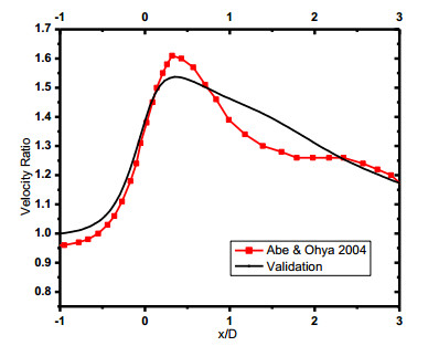
Abe KI, Ohya Y (2004) An investigation of flow fields around flanged diffusers using CFD. J Wind Eng Ind Aerodyn 92: 315-330. doi: 10.1016/j.jweia.2003.12.003
    [32] Mansour K, Meskinkhoda P (2014) Computational analysis of flow fields around flanged diffusers. J Wind Eng Ind Aerodyn 124: 109-120. doi: 10.1016/j.jweia.2013.10.012
    [33] Srikanth KS, Tushar (2016) Numerical analysis of wind lens. Int J Innov Res Sci Eng Technol 5: 759-764.
    [34] Wang W-Q, Song K, Yan Y (2019) Influence of interaction between the diffuser and rotor on energy harvesting performance of a micro-diffuser-augmented hydrokinetic turbine. Ocean Eng 189: 106293. doi: 10.1016/j.oceaneng.2019.106293
    [35] Göltenbott U, Ohya Y, Yoshida S, et al. (2017) Aerodynamic interaction of diffuser augmented wind turbines in multi-rotor systems. Renew Energy 112: 25-34. doi: 10.1016/j.renene.2017.05.014
    [36] Yunus A (2010) Fluid mechanics fundamentals and applications, Boston, Tata McGraw Hill Education Private Limited.
    [37] Owisa F, Badawyb MTS, Abedb KA, et al. (2015) Numerical investigation of loaded and unloaded diffuser equipped with a flange. Int J Sci Eng Res 6: 312-341.
  • This article has been cited by:

    1. Z. Kaseb, H. Montazeri, Data-driven optimization of building-integrated ducted openings for wind energy harvesting: Sensitivity analysis of metamodels, 2022, 258, 03605442, 124814, 10.1016/j.energy.2022.124814
    2. Tesfaye (Shiferaw) Sida, Will Ethiopia be a springboard or a stonewall for GM crops in Africa?, 2021, 39, 1087-0156, 147, 10.1038/s41587-021-00827-5
    3. K. Ramesh Kumar, M. Selvaraj, 2021, 106, 978-3-0357-3628-1, 121, 10.4028/www.scientific.net/AST.106.121
    4. Ngwarai Shambira, Golden Makaka, Patrick Mukumba, Velocity Augmentation Model for an Empty Concentrator-Diffuser-Augmented Wind Turbine and Optimisation of Geometrical Parameters Using Surface Response Methodology, 2024, 16, 2071-1050, 1707, 10.3390/su16041707
    5. Debela Alema Teklemariyem, Eshetu Tadesse Yimer, Venkata Rammaya Ancha, Balewgize Amare Zeru, A CFD parametric investigation on velocity increment induced by an empty diffuser with circumferential holes for horizontal axis wind turbine applications, 2024, 11, 2331-1916, 10.1080/23311916.2024.2386382
    6. Debela Alema Teklemariyem, Eshetu Tadesse Yimer, Venkata Rammaya Ancha, Balewgize Amare Zeru, Parametric study of an empty diffuser geometric parameters and shape for a wind turbine using CFD analysis, 2024, 10, 24058440, e26782, 10.1016/j.heliyon.2024.e26782
    7. Saad A. Mutasher, Husham M. Ahmed, 2023, CFD Analysis of Brimmed Diffuser Augmented Wind Turbine, 979-8-3503-2709-0, 1, 10.1109/ICETAS59148.2023.10346393
    8. Zahra Adnan Shawket, Suad Hassan Danook, Overview Improving the Efficiency of a Wind Turbine by Using a Nozzle and Solar Radiation, 2025, 26665190, 100191, 10.1016/j.uncres.2025.100191
  • Reader Comments
  • © 2019 the Author(s), licensee AIMS Press. This is an open access article distributed under the terms of the Creative Commons Attribution License (http://creativecommons.org/licenses/by/4.0)
通讯作者: 陈斌, bchen63@163.com
  • 1. 

    沈阳化工大学材料科学与工程学院 沈阳 110142

  1. 本站搜索
  2. 百度学术搜索
  3. 万方数据库搜索
  4. CNKI搜索

Metrics

Article views(4477) PDF downloads(738) Cited by(8)

Figures and Tables

Figures(19)  /  Tables(5)

Other Articles By Authors

/

DownLoad:  Full-Size Img  PowerPoint
Return
Return

Catalog