A photovoltaic (PV)-based generator is a crucial component of modern electricity grids. Most PV systems utilize various maximum power point tracking (MPPT) algorithms to inject the maximum available power into the utility. However, on sunny days, consistently obtaining maximum power can lead to increased thermal stress and a reduced reliability of the power electronic-based DC-DC converter. This paper presents a thermal model for the DC-DC converter that evaluates the accumulated temperature based on power losses and ambient temperature sensed by the thermal sensor. A thermal control strategy is suggested to maintain the temperature of the converter's main components within allowable limits. The thermal control includes two stages: a primary stage that adjusts the switching frequency of the IGBT switches to decrease the accumulated temperature and a secondary stage that adjusts the current-based MPPT algorithm to reduce the maximum current through the main switch. This approach aims to extend the lifespan of the utilized DC-DC converter and lower its operational cost. Furthermore, the allowable range for switching frequency variation is determined through a stability analysis of the frequency response, which is evaluated using a Bode plot for the closed-loop system. The proposed thermal control was implemented in a MATLAB/Simulink environment. The associated results demonstrate the effectiveness of the proposed control in maintaining temperature within acceptable limits and thereby improving the reliability of the system.
Citation: Rasool M. Imran, Kadhim Hamzah Chalok, Siraj A. M. Nasrallah. Innovative two-stage thermal control of DC-DC converter for hybrid PV-battery system[J]. AIMS Electronics and Electrical Engineering, 2025, 9(1): 26-45. doi: 10.3934/electreng.2025002
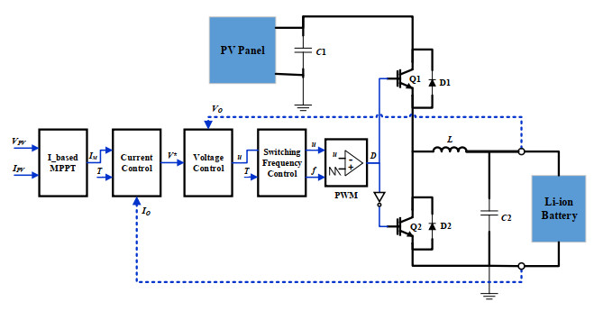
A photovoltaic (PV)-based generator is a crucial component of modern electricity grids. Most PV systems utilize various maximum power point tracking (MPPT) algorithms to inject the maximum available power into the utility. However, on sunny days, consistently obtaining maximum power can lead to increased thermal stress and a reduced reliability of the power electronic-based DC-DC converter. This paper presents a thermal model for the DC-DC converter that evaluates the accumulated temperature based on power losses and ambient temperature sensed by the thermal sensor. A thermal control strategy is suggested to maintain the temperature of the converter's main components within allowable limits. The thermal control includes two stages: a primary stage that adjusts the switching frequency of the IGBT switches to decrease the accumulated temperature and a secondary stage that adjusts the current-based MPPT algorithm to reduce the maximum current through the main switch. This approach aims to extend the lifespan of the utilized DC-DC converter and lower its operational cost. Furthermore, the allowable range for switching frequency variation is determined through a stability analysis of the frequency response, which is evaluated using a Bode plot for the closed-loop system. The proposed thermal control was implemented in a MATLAB/Simulink environment. The associated results demonstrate the effectiveness of the proposed control in maintaining temperature within acceptable limits and thereby improving the reliability of the system.

| [1] |
Naidu IES, Srikanth S, Rao A, Venkatanarayana (2023) A novel mine blast optimization algorithm (MBOA) based MPPT controlling for grid-PV systems. AIMS Electron Electr Eng 7: 135‒155. https://doi.org/10.3934/electreng.2023008 doi: 10.3934/electreng.2023008

|
| [2] |
Moon SY, Chandrarathna SC, Shafique A, Lee JW (2024) A compact DC-DC converter with pulse-counting MPPT and fast one-path self-startup for thermal energy harvesting. IEEE Trans Circuits Syst I Reg Papers 71: 2457‒2470. https://doi.org/10.1109/TCSI.2024.3377003 doi: 10.1109/TCSI.2024.3377003
|
| [3] |
Gabriel OE, Huitink DR (2023) Failure mechanisms driven reliability models for power electronics: A review. J Electron Packag 145: 020801. https://doi.org/10.1115/1.4055774 doi: 10.1115/1.4055774
|
| [4] |
Shen J, Zhang J, Huang X, Qiu L, Fang Y (2023) Active thermal management method for output-parallel DAB DC–DC converters under parameter mismatches and asymmetrical modulation. IEEE Trans Power Electron 38: 8237‒8248. https://doi.org/10.1109/TPEL.2023.3266287 doi: 10.1109/TPEL.2023.3266287
|
| [5] |
Van der Broeck CH, De Doncker RW (2019) Thermal monitoring of power electronic modules with minimal sensing effort. IEEE Energy Conversion Congress and Exposition (ECCE), 5989‒5996. https://doi.org/10.1109/ECCE.2019.8912612 doi: 10.1109/ECCE.2019.8912612
|
| [6] | Li J, Hu G, Ma F, Qiu R, Chen J (2023) Research on IGBT junction temperature prediction method based on Extended Kalman Filtering. International Conference on Wireless Power Transfer, 181‒188. https://doi.org/10.1007/978-981-97-0869-7_19 |
| [7] |
Dou Y (2021) An improved prediction model of IGBT junction temperature based on backpropagation neural network and Kalman filter. Complexity 2021: 5542889. https://doi.org/10.1155/2021/5542889 doi: 10.1155/2021/5542889
|
| [8] | Marquez A, Leon JI, Vazquez S, Franquelo LG (2018) Closed-loop active thermal control via power routing of parallel DC-DC converters. IEEE 12th International Conference on Compatibility, Power Electronics and Power Engineering (CPE-POWERENG 2018), 1‒6. https://doi.org/10.1109/CPE.2018.8372586 |
| [9] |
Ozkan G, Papari B, Hoang PH, Deb N, Edrington CS (2019) An active thermal control method for AC-DC power converter with sequence-based control approach. IEEE Electric Ship Technologies Symposium (ESTS), 263‒267. https://doi.org/10.1109/ESTS.2019.8847886 doi: 10.1109/ESTS.2019.8847886
|
| [10] |
Vitale G, Lullo G, Scirè D (2020) Thermal stability of a DC/DC converter with inductor in partial saturation. IEEE Trans Ind Electron 68: 7985‒7995. https://doi.org/10.1109/TIE.2020.3014580 doi: 10.1109/TIE.2020.3014580
|
| [11] |
Prasobhu PK, Buticchi G, Brueske S, Liserre M (2016) Gate driver for the active thermal control of a DC/DC GaN-based converter. IEEE Energy Conversion Congress and Exposition (ECCE), 1‒8. https://doi.org/10.1109/ECCE.2016.7855131 doi: 10.1109/ECCE.2016.7855131
|
| [12] |
Imran RM, Chalok KH (2024) Innovative mode selective control and parameterization for charging Li-ion batteries in a PV system. AIMS Energy 12: 822‒839. https://doi.org/10.3934/energy.2024039 doi: 10.3934/energy.2024039
|
| [13] |
Alavi O, Rajabloo T, De Ceuninck W, Daenen M (2022) Non-isolated DC-DC converters in fuel cell applications: Thermal analysis and reliability comparison. Applied Sciences 12: 5026. https://doi.org/10.3390/app12105026 doi: 10.3390/app12105026
|
| [14] |
Kalker S, Ruppert LA, Van Der Broeck CH, Kuprat J, Andresen M, Polom TA, et al. (2021) Reviewing thermal-monitoring techniques for smart power modules. IEEE J Emerg Sel Topics Power Electron 10: 1326‒1341. https://doi.org/10.1109/JESTPE.2021.3063305 doi: 10.1109/JESTPE.2021.3063305
|
| [15] | Andresen M, Buticchi G, Liserre M (2016) Active thermal control of isolated soft switching DC/DC converters. IECON 2016-42nd Annual Conference of the IEEE Industrial Electronics Society, 6818‒6823. https://doi.org/10.1109/IECON.2016.7793676 |
| [16] |
Kadandani NB, Dahidah M, Ethni S, Muhammad M (2021) Lifetime and reliability improvements in modular multilevel converters using controlled circulating current. J Power Electron 21: 1611‒1620. https://doi.org/10.1007/s43236-021-00297-7 doi: 10.1007/s43236-021-00297-7
|
| [17] |
Wang Q, Liu J, Wu P, Qin X (2023) A lifetime improvement active thermal control strategy for wind turbine parallel converters based on reactive circulating current. Electronics 12: 3125. https://doi.org/10.3390/electronics12143125 doi: 10.3390/electronics12143125
|
| [18] |
Gonzalez JO, Alatise O (2017) Impact of the gate driver voltage on temperature sensitive electrical parameters for condition monitoring of SiC power MOSFETs. Microelectronics Reliability 76: 470‒474. https://doi.org/10.1016/j.microrel.2017.06.082 doi: 10.1016/j.microrel.2017.06.082
|
| [19] |
Andresen M, Ma K, Buticchi G, Falck J, Blaabjerg F, Liserre M (2018) Junction temperature control for more reliable power electronics. IEEE Trans Power Electron 33: 765‒776. http://dx.doi.org/10.1109/TPEL.2017.2665697 doi: 10.1109/TPEL.2017.2665697
|
| [20] | Peyghami S, Davari P, Blaabjerg F (2018) System-level lifetime-oriented power sharing control of paralleled DC/DC converters. IEEE Applied Power Electronics Conference and Exposition (APEC), 1890‒1895. https://doi.org/10.1109/APEC.2018.8341275 |
| [21] |
Wang R, Huang X, Li J (2021) Active thermal management for SiC MOSFETs based on equivalent adjustment of buffer capacitor. IEEE Trans Circuits Syst. Ⅱ Express Briefs 69: 1502‒1506. https://doi.org/10.1109/TCSⅡ.2021.3135273 doi: 10.1109/TCSⅡ.2021.3135273
|
| [22] |
Wang B, Zhou L, Zhang Y, Wang K, Du X, Sun P (2017) Active junction temperature control of IGBT based on adjusting the turn-off trajectory. IEEE Trans Power Electron 33: 5811‒5823. https://doi.org/10.1109/TPEL.2017.2749383 doi: 10.1109/TPEL.2017.2749383
|
| [23] |
Prasobhu PK, Raveendran V, Buticchi G, Liserre M (2018) Active thermal control of GaN-based DC/DC converter. IEEE Trans Ind Appl 54: 3529‒3540. http://dx.doi.org/10.1109/TIA.2018.2809543 doi: 10.1109/TIA.2018.2809543
|
| [24] | Falck J, Andresen M, Liserre M (2015) Active thermal control of IGBT power electronic converters. IECON 2015-41st Annual Conference of the IEEE Industrial Electronics Society, 1‒6. http://dx.doi.org/10.1109/IECON.2015.7392925 |
| [25] | Ahsan S, Mughal A, Rapiz M (2022) Controlling temperature of DC-DC converter using switching frequency adjustment, Electrical Engineering Department at California Polytechnic State University. Available from: https://digitalcommons.calpoly.edu/eesp/554 |
| [26] |
Hanini W, Ayadi M (2021) Electrothermal modeling of the Insulated Gate Bipolar Transistor (IGBT) using PSpice: Application to DC–DC converter. J Control Autom Electr Syst 32: 507‒521. https://doi.org/10.1007/s40313-020-00672-y doi: 10.1007/s40313-020-00672-y
|
| [27] | Cao R, Li Y, Zhang Y, Liu X, Lv C, Zhang J (2020) Thermal modeling of power semiconductor devices with heat sink considering ambient temperature dynamics. IEEE 9th International Power Electronics and Motion Control Conference (IPEMC2020-ECCE Asia), 290‒295. https://doi.org/10.1109/IPEMC-ECCEAsia48364.2020.9367773 |
| [28] |
Ma K, He N, Liserre M, Blaabjerg F (2015) Frequency-domain thermal modeling and characterization of power semiconductor devices. IEEE Trans Power Electron 31: 7183‒7193. http://dx.doi.org/10.1109/TPEL.2015.2509506 doi: 10.1109/TPEL.2015.2509506
|
| [29] | Erickson RW, Maksimovic D (2020) Fundamentals of power electronics, 3rd Ed., Cham, Switzerland. http://dx.doi.org/10.1007/978-3-030-43881-4 |
| [30] | Lee J (2015) Basic calculation of a buck converter's power stage. Richtek Technol Corp AN041: 1‒8. Available from: http://acots.info/pdf/an041_en.pdf |
| [31] | Ciappa M, Fichtner W (2000) Lifetime prediction of IGBT modules for traction applications. IEEE 38th Annual International Reliability Physics Symposium (Cat. No. 00CH37059), 210‒216. https://doi.org/10.1109/RELPHY.2000.843917 |


Figures(13) / Tables(2)

Rasool M. Imran, Kadhim Hamzah Chalok, Siraj A. M. Nasrallah. Innovative two-stage thermal control of DC-DC converter for hybrid PV-battery system[J]. AIMS Electronics and Electrical Engineering, 2025, 9(1): 26-45. doi: 10.3934/electreng.2025002


 DownLoad: