Loading [Contrib]/a11y/accessibility-menu.js
Research article Special Issues

Performance and Thermal Stability of a Polyaromatic Hydrocarbon in a Simulated Concentrating Solar Power Loop

  • Because polyaromatic hydrocarbons show high thermal stability, an example of these compounds, phenylnaphthalene, was tested for solar thermal-power applications. Although static thermal tests showed promising results for 1-phenylnaphthalene, loop testing at temperatures to 450 ℃ indicated that the fluid isomerized and degraded at a slow rate. In a loop with a temperature high enough to drive the isomerization, the higher melting point byproducts tended to condense onto cooler surfaces. This would indicate that the internal channels of cooler components of trough solar electric generating systems, such as the waste heat rejection exchanger, may become coated or clogged affecting loop performance. Thus, pure 1-phenylnaphthalene, without addition of stabilizers, does not appear to be a fluid that would have a sufficiently long lifetime (years to decades) to be used in a loop at temperatures significantly greater than the current 400 ℃ maximum for organic fluids. Similar degradation pathways may occur with other organic materials. The performance of a concentrating solar loop using high temperature fluids was modeled based on the National Renewable Laboratory Solar Advisory Model. It was determined that a solar-to-electricity efficiency of up to 30% and a capacity factor of 60% could be achieved using a high efficiency collector and 12 h thermal energy storage when run at a field outlet temperature of 550 ℃.

    Citation: Joanna McFarlane, Jason Richard Bell, David K. Felde, Robert A. Joseph III, A. Lou Qualls, Samuel Paul Weaver. Performance and Thermal Stability of a Polyaromatic Hydrocarbon in a Simulated Concentrating Solar Power Loop[J]. AIMS Energy, 2014, 2(1): 41-70. doi: 10.3934/energy.2014.1.41

    Related Papers:

    [1] Chao-Jen Li, Peiwen Li, Kai Wang, Edgar Emir Molina . Survey of Properties of Key Single and Mixture Halide Salts for Potential Application as High Temperature Heat Transfer Fluids for Concentrated Solar Thermal Power Systems. AIMS Energy, 2014, 2(2): 133-157. doi: 10.3934/energy.2014.2.133
    [2] Duong Van, Diaz Gerardo . Carbon dioxide as working fluid for medium and high-temperature concentrated solar thermal systems. AIMS Energy, 2014, 1(1): 99-115. doi: 10.3934/energy.2014.1.99
    [3] Xian-long Meng, Cun-liang Liu, Xiao-hui Bai, De-hai Kong, Kun Du . Improvement of the performance of parabolic trough solar concentrator using freeform optics and CPV/T design. AIMS Energy, 2021, 9(2): 286-304. doi: 10.3934/energy.2021015
    [4] Saad Eddin Lachhab, A. Bliya, E. Al Ibrahmi, L. Dlimi . Theoretical analysis and mathematical modeling of a solar cogeneration system in Morocco. AIMS Energy, 2019, 7(6): 743-759. doi: 10.3934/energy.2019.6.743
    [5] Thomas Wetzel, Julio Pacio, Luca Marocco, Alfons Weisenburger, Annette Heinzel, Wolfgang Hering, Carsten Schroer, Georg Muller, Jurgen Konys, Robert Stieglitz, Joachim Fuchs, Joachim Knebel, Concetta Fazio, Markus Daubner, Frank Fellmoser . Liquid metal technology for concentrated solar power systems: Contributions by the German research program. AIMS Energy, 2014, 2(1): 89-98. doi: 10.3934/energy.2014.1.89
    [6] Daniel Chuquin-Vasco, Cristina Calderón-Tapia, Nelson Chuquin-Vasco, María Núñez-Moreno, Diana Aguirre-Ruiz, Vanesa G. Lo-Iacono-Ferreira . Mathematical modeling of a binary ORC operated with solar collectors. Case study—Ecuador. AIMS Energy, 2023, 11(6): 1153-1178. doi: 10.3934/energy.2023053
    [7] Hayder S. Al-Madhhachi, Ahmed M. Ajeena, Nihad A. Al-Bughaebi . Dynamic simulation and energy analysis of forced circulation solar thermal system in two various climate cities in Iraq. AIMS Energy, 2021, 9(1): 138-149. doi: 10.3934/energy.2021008
    [8] Muluken Biadgelegn Wollele, Abdulkadir Aman Hassen . Design and experimental investigation of solar cooker with thermal energy storage. AIMS Energy, 2019, 7(6): 957-970. doi: 10.3934/energy.2019.6.957
    [9] Wei An, Yifan Zhang, Bo Pang, Jun Wu . Synergistic design of an integrated pv/distillation solar system based on nanofluid spectral splitting technique. AIMS Energy, 2021, 9(3): 534-557. doi: 10.3934/energy.2021026
    [10] Angelo Minotti . Hybrid energy converter based on swirling combustion chambers: the hydrocarbon feeding analysis. AIMS Energy, 2017, 5(3): 506-516. doi: 10.3934/energy.2017.3.506
  • Because polyaromatic hydrocarbons show high thermal stability, an example of these compounds, phenylnaphthalene, was tested for solar thermal-power applications. Although static thermal tests showed promising results for 1-phenylnaphthalene, loop testing at temperatures to 450 ℃ indicated that the fluid isomerized and degraded at a slow rate. In a loop with a temperature high enough to drive the isomerization, the higher melting point byproducts tended to condense onto cooler surfaces. This would indicate that the internal channels of cooler components of trough solar electric generating systems, such as the waste heat rejection exchanger, may become coated or clogged affecting loop performance. Thus, pure 1-phenylnaphthalene, without addition of stabilizers, does not appear to be a fluid that would have a sufficiently long lifetime (years to decades) to be used in a loop at temperatures significantly greater than the current 400 ℃ maximum for organic fluids. Similar degradation pathways may occur with other organic materials. The performance of a concentrating solar loop using high temperature fluids was modeled based on the National Renewable Laboratory Solar Advisory Model. It was determined that a solar-to-electricity efficiency of up to 30% and a capacity factor of 60% could be achieved using a high efficiency collector and 12 h thermal energy storage when run at a field outlet temperature of 550 ℃.


    1. Introduction

    Solar power collection can be divided into two main technologies, those that directly convert sunlight to electrons, such as photovoltaics, and those that heat a transfer medium or fluid that passes through a power cycle to produce electricity. Concentrating solar power(CSP)has an advantage over direct conversion solar technologies of having inherent energy storage because of the heat carrying capacity of the thermal fluid, allowing the system to operate during periods of low or no solar irradiance. CSP technologies include troughs, power towers, parabolic disks, and Fresnel concentrators [1]. In the work described here, the goal was to investigate the replacement of organic fluids in trough solar electric generation systems(SEGS)with fluids that can be used at higher temperatures.

    Solar trough collectors concentrate solar power on a central receiver using a parabolic mirror that can rotate about a single axis. The high emissivity stainless steel receiver encapsulates a fluid that flows through the collector and passes to a heat exchanger for power generation. The collector itself is encased in a vacuum envelope that permits solar radiation to pass through, but minimizes the transmission of infrared(IR). Trough SEGS plants have operated successfully in the United States from 1984 to the present day, producing up to 80 MWe from individual solar fields, such as the Acciona Solar One plant near Boulder City, NV, a 75 MW facility. IvanPah in California[2] and Solana [3]in Arizona are ex pected to produce 377 and 280 MW respectively. Trough SEGShave also been deployed or planned by Abengoa in Spain(200 MW)[4] and Negev in Israel(110 MW)[5].

    The thermal performance of CSP trough plants is limited by the efficiencies of photon capture and conversion of sunlight to heat and the thermal-to-electric conversion. The first of these factors decreases with increasing temperature due to radiative heat loss, while the second increases with fluid temperature at a given heat rejection temperature. These efficiencies, in turn, depend on the geometry of the collector, the properties of the heat transfer fluid(HTF), the thermal performance of the solar receiver, and the operation of the power cycle. In this paper, we focus on the thermal performance of the HTF. Higher temperatures in the loop allow better thermodynamics of conversion and also improve the operation of the turbines on the secondary side because of higher quality steam.

    Fluid decomposition is one of the prime limitations on the performance of a trough CSP system over years of operation. Degradation of the vacuum envelope because of hydrogen ingress from fluid breakdown increases thermal conductivity and reduces the efficiency of the collector; an example is given by Reaction 1.

    C16H12(phenylnaphthalene)®C16H14(fluoranthene)+ H2 (1)

    Ideal fluids for CSP will be those that have a large liquid range, fluidity at the coolest portion of the solar loop along with a relatively low pressure in the hottest zone, a thermal stability to allow years of operation with minimal replacement or recovery, and that are chemically inert to materials in the loop. Commonly-used thermal oils, biphenyl oxides and terphenyls, are limited to maximum operating temperatures below 400°C, which is less than ideal for most power-generation steam turbines [6]. High-temperature organic Rankine cycles use alkanes [7,8], aromatics, and linear siloxanes to ext ract heat from thermal systems up to 350 °C . Molten salt HTF can operate as high as 550°C, which is similar to modern gas or coal-fired steam cycles [9]. However, inorganic molten salts have very high freezing temperatures [10], making them unsuitable for use in CSP trough applications except as thermal storage media. Ionic liquids, organic salts that are molten at temperatures below 100 °C, have been considered for thermal solar applications [11]. Fluids enhanced by entrained nanoparticles are being studied at a conceptual and lab-scale level, but large-scale performance data have not yet been obtained [12,13]. Scanning and tunneling microscopy studies have indicated that nanoparticles increase the specific heat of the fluid and allow the formation of percolation networks because of their high specific surface area [14]. If one of these approaches leads to a suitable high-temperature HTF, this should allow a reduction in the cost of energy production from CSP plants by increasing the system temperature, and , thus, power cycle efficiency.

    Examples of HTFs for power generation are given in Table. 1 along with important thermophysical properties such as phase change temperatures. Factors that affect heat transfer such as thermal conductivity and loop performance, such as dynamic viscosity, are also given in the table. These fluids cover a range of operating temperatures, so the temperature associated with the listed properties is given in the first column to help with the comparison.

    Table 1. Thermophysical properties of heat transfer fluids for power generation.
    Compound Tm Tb(K) Liquid Cp (kJ·kg-1K-1) Liquid r(kg·m-3) Tc(K)Pc(bar) Vapor Pressure(bar) Thermal conductivity λ(W·m-1·K-1) Dynamic viscosity υ(mPa·s)
    dmaximum operating temperature, above which decomposition occurs
    Dowtherm A @ 678 K [15] 285.2 530.2 2.725 672.5 770 31.34 11.32 0.0771 0.12
    Xceltherm 600‑C20 paraffin oil @ 588.8 K [7,8] Tb range 574- 741 3.001 672.36 768 10.7 0.250 0.1122 0.252
    H2O @ 563K, 7.5MPa [16] 273.15 373.15 5.5 732 646.95 220.64 Super- heated 0.56 0.13
    Biphenyl @ 500 K [17,18,19] 342 559 2.03 869 773 ± 3 33.8 ± 1 0.531 0.118 0.32
    p-Terphenyl @ 500 K [17,18,19,20] 485 623 1.98 947 908 + 10 29.9 ± 6 0.0199 0.135 0.73
    Therminol VP1 Biphenyl & diphenyl oxides @600 K [21] 285 530 2.39 788 772 33.1 3.8 0.0912 0.1958
    Therminol 66 Mix of hydrogenated terphenyls @600 K [22] 266 632 2.67 786 842 24.3 0.542 0.911 0.359
    Hitex XL Ca(NO3)2/NaNO3/KNO3 42/15/43 wt.% @ 600K [23,24,25] 413 823d 1.44 1970 NA NA 0.519 4.8
    1-phenylnaphthalane @ 600K [26] 297-318 598 2.6 849 818 7.1 0.820 0.077 0.11
    2-phenylnaphthalene @ 600K [26] 375 627 2.4 837 831 6.5 0.563 0.083 0.11
     | Show Table
    DownLoad: CSV

    Polyaromatic hydrocarbons comprise some of the most stable organic compounds in regards to temperature and resistance to oxidation and are expected to have desirable thermophysical properties and stabilities up to at least 500 °C [17,27]. For instance, the European Union has m and ated that these compounds be removed from diesel fuel because they can pass intact through combustion in a compression engine. Substituted naphthalenes, in particular, have measured high thermal stabilities, a liquid range from room temperature to several hundred degrees Celsius and high critical points, along with a low propensity to oxidation or degradation. The properties of 1-phenylnaphthalene and its isomer, 2-phenylnaphthalene are included in Table. 1.

    Thermophysical data collected on laboratory samples under well controlled conditions can be used to survey fluids that have potential for large-scale CSP and these have been reviewed in detail by Zalba and coworkers [28]; however, physical property measurements do not probe transient effects such as the slow kinetic conversions, non-equilibrium processing, and reactions with collector materials. Slow kinetics can be difficult to study, as small changes in fluid composition need to be detected over long periods of time. Hence, laboratory-scale engineering tests on the use of substituted naphthalenes as heat transfer fluids for concentrating solar power applications were done under conditions relevant to SEGS operation.

    The fluids were evaluated by:(1)testing the chemical stability and thermophysical properties of c and idate heat transfer fluids by repetitive cycling to temperatures up to 500 °C;(2)testing the performance of c and idate heat transfer fluids in an instrumented flow loop; and (3)development of a kinetic model to explain the results of the testing. The tests conducted here represent an intermediate step in the investigation of organic fluid performance. Samples collected after days and weeks of operation were chemically analyzed for degradation products and the chemistry of the fluid was modeled using a chemical kinetics model.

    2. Materials and Methods

    From laboratory measurements and calculations of thermophysical properties, it was thought that substituted phenylnaphthalenes may have a combination of sufficiently high thermal stability and sufficiently low melting temperatures to be suitable for concentrating solar power(CSP)loop operation at temperatures up to and above 500 °C [26]. In particular, the high critical temperatures and low vapor pressures of 1-phenylnaphthalene appeared to be advantageous relative to other polyaromatic hydrocarbons. The performance of the phenylnaphthalene fluid, with and without additives, was tested in two ways in the laboratory. One method used a static cell that was heated continuously over a number of weeks and the other used a small-scale loop that cycled the fluid through temperatures over 400 °C to below room temperature over a week of operation. Degradation of the fluid was monitored by taking grab samples for chemical analysis.

    2.1 . Synthesis

    Although 1-phenylnaphthalene may be isolated during the refining of petroleum [29,30], for the purposes of this work a synthetic route was chosen to ensure purity of the fluid being tested. 1-phenylnaphthalene was synthesized by a modified Suzuki-Miyaura coupling reaction[31], where an aryl halide joins to an organometallic precursor over a palladium catalyst, Scheme 1. The Suzuki coupling mechanism was chosen because it offers a simple process that can be carried out in the laboratory under mild conditions yet gives high yields and purity[32,33,34,35,36]. Modifications were made when applying the as-published coupling synthesis. It was found that Pd(II)acetate was more stable than Pd(0)towards deactivation and so served as a more effective catalyst. In addition, literature syntheses suggested the use of acetone. However, n-propanol was used instead, as acetone was found not to give a quantitative yield.

    FigureS 1. 1-phenylnaphthalene synthesis by Suzuki coupling.


    1-Bromonaphthalene(1.0 equiv.) and phenylboronic acid(1.05 equiv.)were dissolved in n-propanol. To this solution aqueous potassium carbonate(1.20 equiv.)was added as a 3 M solution. The catalyst, a mixture of palladium acetate(0.003 equiv.) and tri-(o-tolyl)phosphine(0.009 equiv.), was added and the solution was brought to reflux for one hour. Water was added to the reaction, the phases were separated, and the aqueous phase was extracted three times with diethyl ether. Combined organic extracts were washed with brine, dried over magnesium sulfate, and the solvent was removed under reduced pressure. The brown product was then passed through a short silica plug to remove palladium impurities. The final product was purified by vacuum distillation. The colorless oil was obtained in 99% purity as analyzed by nuclear magnetic resonance(NMR) and gas chromatography-mass selective detection(GC-MSD), and in 95% isolated yield, with the main impurity being the higher boiling point 2-phenylnaphthalene isomer.

    Synthesis of the phenylnaphthalene was scaled up to produce several hundred mL at a time and purified using rotary evaporation to selectively remove the solvent. Even with recycled solvent, the Suzuki synthesis suffers from a low atom economy and is not economical on a large scale. The cost of producing the synthetic oil by the Suzuki coupling mechanism was estimated as ranging from $800 to $1200 per liter, based on the price of similar commodity chemicals or on the cost of the reagents. As this price is about ten times the cost of Therminol 66, ways of reducing the cost were considered. The Kumada coupling alternative has better atom economy and lower cost starting materials than the Suzuki process, but uses more hazardous reagents [37]. It has not been as well vetted in the literature, and there may be a greater chance of side reactions leading to a less pure product.

    2.2. Apparatus and Sample Preparation

    2.2.1. Static Experiments

    Laboratory scale experiments were carried out by heating small amounts of synthetic oil in sealed stainless steel sample vessels for periods of up to 1 month. Heating took place in an inert atmosphere, argon or helium, to test fluid stability under anaerobic conditions.

    Small amounts of synthesized 1-phenylnaphthalene, on the order of 1 mL, were heated in4.9(2)± 0.1(3)mL stainless steel vessels from 400 to 525 °C, usually over a period of one week. The samples were held in thick-walled 316 stainless steel 0.95-cm-outer diameter(OD)tubes that were sealed with welds on the bottom and by flare fittings on the top. The specimen holders were filled with the sample fluid at room temperature in a glove box with an inert argon cover gas. The cover gas pressure in the glove box was controlled at slightly(0.03 bar)above atmospheric pressure. Gravimetry was used to determine volumes of the samples and argon introduced into the cell. After being sealed, the specimen holders were removed from the glove box to be installed in the furnace.

    The furnace comprised an electrically heated copper block suspended from the top plate of a small vacuum chamber to minimize heat losses from conduction, Figure 1. Thermocouples installed into small holes in the copper block allowed direct monitoring of the block temperatures in three locations. Wires from the thermocouples were attached to feedthroughs in the upper Conflat® flange. The copper block was made of three pieces. Two outer pieces clamped to a main body formed six mating vertical holes between the inner and outer sections. The specimen holders were held tightly in these holes by screws that passed through the outer pieces and were threaded into the inner pieces to ensure good thermal contact. Five of the holes were used for the sample vessels previously described, and one was occupied by a 7.60 mL tube that penetrated the furnace upper plate. This exposed tube was used to monitor the temperature and pressure of the fluid during heating. Before sealing, a shroud of aluminum foil was wrapped around the assembly to minimize emissive losses.

    Figure 1. Picture of furnace interior and sample holders.


    Solar heating was not practical for these tests, so heating was achieved using a cartridge heater inserted into a hole centered in the main copper block. A custom-built st and -alone controller was used to monitor the block temperature and control the current through the heater. The temperature was controlled manually using fixed current settings or with a proportional-integral-derivative(PID)controller algorithm to within ± 0.5 °C. The temperature of the sample was estimated as the mean of the temperatures of the inner and outer thermocouples, with data recorded every 2 s. Heat up took about 120 min because care was taken not to overshoot the maximum temperature. When steady-state had been reached, the difference between the inner and outer blocks was about 14 °C, and the sample temperature was taken as the average of the two. The error in this calculation was estimated to be no more than ± 5 °C except during heat up, when the temperature of the outer block could lag that of the inner block by up to 50 °C. Cool down, at the end of the test, took several hours after the power was switched off to the heater. Typical ramp-up and cool-down temperature traces are given in Figure 2, and represent the average temperature across the heating block. An irregularity in the temperature trace at 425 °C(18 min)shows where manual control of the heating rate was turned over to the PID controller. Another irregularity at 367 min shows where the temperature set point was readjusted to ensure the fluid was heated above 450 °C. However, temperatures were very stable, even over the month-long heating test at 450 °C, being controlled to within ± 0.5 °C.

    Figure 2. Details of temperature increase after start of heating and temperature decrease at the conclusion of heating for the month long static test.

    Ten static heating tests of at least one week each were performed on 1-phenylnaphthalene, and mixtures of 1-phenylnaphthalene and minor components such as fluoranthene or 2, 2, 6, 6, -tetramethylpiperidinyl-1-oxy(TEMPO), and coupon materials, Table. 2. Coupons representing structural materials that may be found in the trough-type collectors of a CSP plant were introduced in some of the tests, including carbon steel, DIN1.4541 stainless steel, and brass. These coupons were small, on the order of 25-30 mg. Temperature data were taken throughout the heating experiments. After thermal testing, the specimens were cooled, opened to check for gas release, and samples were taken for analysis.

    Table 2.Experimental details of static heating tests on 1-phenylnaphthalene
    (Results presented in Figs.7-9).
    Test Number Minor components Heating Details
    Maximum Temp (± 4 °C) Duration(± 1 h) Coupons
    1 1-3% 2-C16H12 536 29 no
    2 1-3% 2-C16H12 494 169 no
    3 1-3% 2-C16H12 490 165 no
    4a 1-3% 2-C16H12 482 2 no
    4b 1-3% 2-C16H12, TEMPO 482 336 no
    5 3% 2-C16H12, TEMPO, Fluoranthene 536 337 no
    6 1% 2-C16H12, Fluoranthene 385 169 carbon steel, stainless steel, brass
    7 1-3% 2-C16H12, Fluoranthene 454 240 carbon steel, stainless steel, brass
    8 1% 2-C16H12, Fluoranthene 446 175 carbon steel, stainless steel, brass
    9 1% 2-C16H12 500 199 carbon steel stainless steel
    10 1% 2-C16H12, Fluoranthene 500 171 carbon steel stainless steel
     | Show Table
    DownLoad: CSV

    In addition to the heat- and -hold experiments, tests were also conducted by manually ramping the phenylnaphthalene fluid to simulate conditions that would be encountered in a trough CSP loop. These tests involved thermally cycling the samples of synthetic oil between 290 and 450 °C, typical of the thermal cycle in a CSP operation. For the ramping experiments, a second vessel was designed, Figure 3a. The vessel was slightly smaller, 4.82 mL, had much less thermal mass being made of aluminum, and could accommodate two sample holders. These tests were conducted with a flow of helium through the shroud of the chamber to enhance heat up and cool down through convection. With a slight overpressure of helium(2.4 bar)corresponding to a flow rate of 8.5m3·h-1, rates of heating, 20º·min-1, and cooling, 40º·min-1, were achieved between 290 and 450 °C, Figure 3b.

    Figure 3. a)Aluminum cell used for ramping experiments, showing two sample holders and embedded heater. b)Temperature profile for 1 day cycling test.

    2.2.2. Loop Tests

    To test performance of the 1-phenylnaphthalene under flowing conditions and realistic temperature gradients, small scale loop experiments were performed. The apparatus was heated electrically, decoupling investigation of fluid pumpability from solar collection efficiency.

    Theloop was designed to test the stability of high temperature thermal energy storage fluids under thermal cycling conditions, Figure 4. Temperatures of the fluid in the cycle ranged from a maximum at 500 °C, with cooling to 70°C. The loop volume was 600mL, with additional capacity in a reservoir. The apparatus was typically run with 700 mL of fluid. A pneumatically powered, positive displacement, reciprocating injection pump was used to provide stable circulating flow. The pump was rated for 0.19 to 21.3 L·h-1, but was typically operated at the bottom of the range to achieve sufficient heating. The flow rate of fluid through the loop was calibrated using deionized water.

    Figure 4. High temperature loop showing the insulated 2.4 kW heater on the right, the reservoir at the bottom, and the heat exchanger at the top of the loop.

    The heated section used four symmetrically placed 600 W cartridge heaters, Figure 5. The heater was insulated with several layers of insulation to minimize heat loss to the environment. An accumulator with a sight tube provided a visual indication of the liquid level in the system. At temperature, the system was operated at an argon overpressure of 8 bar to suppress bulk boiling of the fluid. Because the loop was to contain high pressure organic fluids, for safety it was contained in an argon filled glove box that was sealed when in operation, with interlocks on the heater power in the event of high temperatures, pressures, or oxygen level in the glove box. Safety was also derived from having a primary system relief valve at 14 bar, a supply tank relief at 1.7 bar, and an argon gas relief valve set at 8.6 bar.

    Figure 5. High-temperature loop heated section showing placement of the 4 × 600 W cartridge heaters.

    2.3. Fluid Analysis

    The polyaromatic test fluid was characterized before and after heating by 1H NMR using a Bruker Avance 400 MHz instrument and by gas chromatography using an Hewlett Packard(HP)5890 gas chromatograph(GC), using either a flame ionization detector(FID)or a mass selective detector(MSD). The NMR was useful in the detection of unreacted starting materials from the Suzuki coupling synthesis, but was less effective in distinguishing one isomer of phenylnaphthalene from another. The methods for the GC FID and the GC MSD are given in Table. 3. The GCs were run using DB5 capillary columns with ultrahigh purity(UHP)helium as a carrier gas(Air Liquide 99.9999%)passed through a desiccating column. Hydrogen for the FID was provided by an on-line Perkin Elmer hydrogen generator. Typical chromatograms from phenylnaphthalene are shown in Figure 6. Retention times were assigned based on the use of calibration runs and by assignment using the ion fragmentation pattern from the GC-MSD. Polyaromatic hydrocarbons do not fragment in the mass spectrometer and have a large molecular ion, M+, thus making them easy to identify. The uncertainty on quantification of the analysis is about ±10%, but is less for the FID than the MSD analysis. Details are given elsewhere.[38]

    Table 3. Gas Chromatography Methods
    GC MSD GC FID
    Injector 250 °C 150 °C
    splitless splitless
    Oven Temperature Program 150-270 °C @ 15°·min-1 150-270 °C @ 15°·min-1
    Hold at 270 °C for 3 min Hold at 270 °C for 3 min
    Detector 340 °C 340 °C
    Column DB5, 30 m, 0.320 mm ID, 0.25 µm DB5, 30 m, 0.530 mm ID, 0.5 µm
    Carrier gas UHP helium @ 44 psig UHP helium @ 40 psig
    Solvent Delay 2.2 min Not applicable
     | Show Table
    DownLoad: CSV
    Figure 6. GC traces showing changes in phenylnaphthalene peaks arising from heating experiments.

    Unheated phenylnaphthalene has a large peak at a retention time of 5.5 min. corresponding to 1-phenylnaphthalene, with a small peak at about 6.2 min from the 2-phenylnaphthalene isomer, Figure 6. Other peaks in the GC at 2.7 and 3.2 min come from unreacted starting material, such as naphthalene at 2.6 min, and byproducts such as biphenyl at 3.2 min. As synthesized, the phenylnaphthalene has a purity of about 99%. Some of the tests were used commercial 1-phenylnaphthalene with 97% purity(Oakwood Products Inc., Lot E06C), but the larger percentage of impurities did not make much difference to the results. After refluxing at 365 °C for a week, the peaks from the impurities disappeared and only those from the two phenylnaphthalene compounds remained. When the sample was heated to 500 °C for a week, isomerization to 2-phenylnaphthalene was observed, with growth in the peaks for naphthalene, phenanthrene, fluoranthene at 6.9 min, and a variety of terphenyls at > 7 min.

    3. Results and Discussion

    3.1.Static Tests

    The results of GC analysis of the static cells, Figure 7, indicated that the synthetic phenylnaphthalenes did not show observable chemical change up to 400 °C. At steady heating for 1 week at 450 °C, significant isomerization to 2-phenylnaphthalene was observed, along with production of some fluoranthene and other breakdown products. Even more sample conversion to fluoranthene and other products happened at 500 °C; however, the rate of conversion was slow and the system did not appear to have reached thermodynamic equilibrium. Some of the samples taken from the 500 °C heating tests were viscous and so were rinsed from the vessels with toluene. Analysis showed more alteration in the rinsed samples than the fluids that were dripped from the vessels after heating - “drips” in Figure 7.

    Figure 7. Effect of temperature on fluid heated for 1 week, showing the mole fraction of chemical species as a function of temperature as measured by GC.

    The effect of adding stabilizing agents was investigated; fluoranthene to reduce the chemical potential driving Reaction(1)(Section 1) and TEMPO, a radical scavenging agent, Figure 8, the weight percent of fluoranthene indicated as “F” on the ordinate. All of these samples were held at 500 °C for over 1 week, except for one sample that was heated for two weeks. The presence or absence of coupons is also indicated.

    Figure 8. GC analysis of samples after heating for 1 week at 500 °C, showing mole fraction of chemical species as a function of temperature as measured by GC. The sample in the 5th row was heated for 2 weeks.

    Samples were compared after one and two weeks of heating(the 7th and 5th rows down respectively) and indicated that there were continual chemical changes throughout the second week of heating, although the product fractions were not dramatically different. Tests with and without coupons of stainless steel and carbon steel indicated that the effect of these materials was small, to within ± 10%, or the error of the measurement. This was not the case for brass, which appeared to catalyze decomposition. Hence, results from tests using carbon steel and stainless steel were averaged in the plot, as they were so similar. The coupons were not analyzed for corrosion, but full consideration of materials interactions would be an important part of follow on work in the testing of fluid performance.

    Fluoranthene converts to phenanthrene, C14H10, as shown by results in the second line from the top. When fluoranthene is mixed with 1-phenylnaphthalene, the isomer 2-phenylnaphthalene appears after a week of heating to 500 °C. Hence the fluoranthene does not appear to suppress isomerization, although terphenyls and binaphthyls were not observed in the tests with large amounts of fluoranthene.

    Both the static and the slow ramping experiments indicate that the 1-phenylnaphthalene fluid appears to be stable to decomposition below 450 °C, although some isomerization can occur. When temperatures are raised to 500 °C and above; however, discernible reactions to other polyaromatic hydrocarbons take place over a week of heating, indicating that the fluid is breaking down. When the sample vessels were opened, a small amount of gas was released likely as volatile aromatic compounds and possibly H2, although most of the sample remained a liquid. Gas sampling was not possible for the static tests because of the propensity of the organic to leak through most compression fittings and valves and so welds and flare fittings were used in the sample vessel.

    The fluid was heated for a month to determine if equilibrium could be reached. The results of the month-long tests are plotted in Figure 9 along with the results from shorter term tests. The results of heating indicate that the 1-phenylnaphthalene first isomerizes to 2-phenylnaphthalene and fluoranthene, which peak in concentration after about 1 week. After that point, the fluid slowly continues to disproportionate either to higher molecular weight polymers or to lower molecular weight fragments and stable aromatics and the 1-phenylnaphthalene concentration levels off at21 ± 2%. The process is accelerated at 500°C(Figure 8)in comparison with 450 °C(Figure 9), but the chemical reaction mechanism appears to be similar.

    Figure 9. Analysis of samples heated for varying lengths of time at 450 °C, showing the mole fraction of chemical species as a function of temperature as measured by GC.

    The results of the thermal cycling tests are given in Table. 4. In each set of tests, to one of the samples was added a small amount of Fe3O4(Met-Chem LLC), to serve as a radical scavenger and , thus, to inhibit propagation of degradation reactions involving benzyl and naphthyl radicals. The addition of 100-nm-dia. Fe3O4 particles had no significant effect on the stability of the 1-phenylnaphthalene as can be seen in the results of the analysis of the fluid before and after heating. For comparison, data for as-synthesized 1-phenylnaphthalene is included in the table, showing the small fraction of 2-phenylnaphthalene that was not removed during purification after synthesis.

    Table 4. Results from cycling 1-phenylnaphthalene
    Sample Mole fraction 1-phenylnaphthalene Mole fraction 2-phenylnaphthalene
    I-1 0.960 0.040
    I-1(repeat) 0.979 0.021
    I-2(with Fe3O4) 0.978 0.022
    II-1 0.979 0.021
    II-2(with Fe3O4) 0.982 0.018
    Average thermally cycled 0.976 ± 0.009 0.024 ± 0.009
    Unheated 0.986 0.014
     | Show Table
    DownLoad: CSV

    Although the samples appeared to be fairly stable under thermal cycling, visual inspection indicated a qualitative difference between the samples with and without the addition of Fe3O4 nanoparticles. Fluids without the particles appeared to be turbid and indicated some carbonization, whereas the fluids with the particles were clear. Such sediment formation would not be apparent in the results of the GC-MS, but the visual darkening indicates the formation of larger molecular weight carbon molecules, likely arising from the recombination of aromatic radicals and precipitation of quadriphenyls and larger species. These species are non-volatile in the GC-MSD, but there is evidence of terphenyl formation at longer times and higher temperatures, Figures 7-9. The nanoparticles may have prevented the formation of larger molecular weight aromatics.

    In these tests, analysis of the head space was not possible, although gas release was apparent when some of the sample vessels were opened after a heating cycle. Hence, 1-phenylnaphthalene was analyzed by pyrolysis GC to determine if gaseous breakdown products could be identified. In this technique the sample is ramped very quickly to a high temperature, in this case 600 °C, with online analysis using GC-MSD. However, as in the case of earlier thermophysical property measurements, the decomposition of 1-phenylnaphthalene was found to be a relatively slow process, and the pyrolysis GC-MS simply demonstrated the volatility of the synthetic oil as a function of temperature.

    Although the temperature range of stability was not as high as expected from the thermodynamic data on small samples, from these tests it appeared as if 1-phenylnaphthalene had potential as a c and idate heat transfer fluid up to 450 °C, if not above, and so could be used to increase the thermodynamic efficiency of a high temperature solar collector for CSP applications. Thus, bench-scale tests were scaled up to samples of several hundred mL to be circulated in an electrically heated loop.

    3.2. Loop Tests

    The loop heating tests are summarized in Table. 5. The temperature, pressure and heater power were monitored and recorded continuously by the system throughout the tests, which ran for up to 1 week.

    Table 5.Heating tests using high-temperature loop
    Fluid Fluid temperatures(min-max)°C Duration(h) Flow Rate(mL·min-1) Notes
    Therminol 66 17-310 200 196
    1-phenylnaphthalene 18-401 200 182
    1-phenylnaphthalene 18-475(set at 450) 38 147 plugged at cold leg
    1-phenylnaphthalene 435(set at 420) 156 147 water heater added to increase cold leg temperature
     | Show Table
    DownLoad: CSV

    Temperature data for the Therminol 66 test and the 400 °C 1-phenylnaphthalene test are given in Figures 10a and b respectively. The bulk fluid temperature is the red line, more than 100 °C lower than the thermocouple embedded in the heater wall. The pump inlet represents the lowest temperature of the system, after passing through the heat exchanger. The system pressure was monitored close to the pump discharge and remained at about 7 bar during a run.

    Figure 10. Temperature traces during loop heating of Therminol 66 and 1-phenylnapthalene respectively.

    Operation for an extended period of time illustrated how changing fluid composition can affect pumpability and flow. The second 1-phenylnaphthalene test ended early because the system became plugged on the cold leg and the temperature rose to 475 °C, beyond the set point at 450°C, and shut down the heater on the high temperature trip point. The third test shut down in the same manner, with an excursion in temperature from 433 to 460 °C in 1 second, with a maximum temperature of 514°C reached 40 s later. However, in this case, the pump also tripped on a low-pressure interlock, indicating a blockage. After the first blockage incident, it was apparent that even small amounts of 2-phenylnaphthalene conversion product would precipitate at the entrance to the pump, where flow is restricted and temperatures are below the freezing point. Hence a 9 kW heater was installed on the chilled cooling water, to increase the temperature to 45-46 °C from the 4-5 °C on previous tests. This modification allowed the final test to run for almost a week, but eventually that one shut down as well.

    Samples were taken of the loop fluids after heating, Table. 6, and analyzed using GC-MS, Figure 11. Although some discoloration was noted from the test at 400 °C, the fluid was found to be largely unaltered. Because of the cost of the fluid and the need to test long term stability, the fluid was reused for the test at 450 °C without purification. Following the test at 450 °C, however, the heat transfer fluid was redistilled to remove impurities before the test at 420 °C, reducing the residual amount of 2-phenylnaphthalene to 6%.

    Table 6. Samples taken for chemical analysis after loop testing
    Sample ID Comments
    400-1 400 °C, slight discoloration after heating
    450-1 450-2 450-3 450-4 450-5 450 °C, sample from clogged filter, semi-solid 450 °C, fluid in reservoir 450 °C, fluid in drain leg 450 °C, fluid in drain leg 450 °C, sample from heat exchanger, semi-solid
    420-1 420-2 420-3 420-4 redistilled sample, taken prior to heating 420 °C, fluid upstream of pump 420 °C, sample from cold side of heat exchanger 420 °C, sludge from heat exchanger, semi-solid
     | Show Table
    DownLoad: CSV
    Figure 11. Analysis of samples heated in the loop test, showing the mole fraction of chemical species as a function of temperature as measured by GC.

    Results from the tests at 450 and 420°C, Figure 11, indicate that the sampling location had a significant bearing on the results of the analysis. The most highly altered fluid was found in sludges from the cold leg and filter, where the samples taken included yellow solid precipitates. Fluids from the reservoir or drain leg showed much less conversion. In all of these samples, the observed conversions were less than for fluids held continuously at 450 °C, Figure 7, where levels of 1-phenylnaphthalene dropped to 17% over 1 week. This suggested that the kinetics of transformation were slowed during the thermal cycling. However, the flow system could not tolerate even modest amounts of 2-phenylnaphthalene before blockages formed.

    4. Chemical Kinetics Model

    Thermodynamic considerations indicate that of the main polyaromatic hydrocarbons detected in the loop after heating, fluoranthene would be more stable than 2-phenylnaphthalene, which is in turn more stable than 1-phenylnaphthalene. The Gibbs energy of isomerization has a linear temperature dependence for both the liquid and gaseous phases, as given in Equation(1a, b), from T = 375 to 600 K(102-327 ºC). Although thermodynamic considerations do not drive the kinetics of conversion directly, given enough time one would expect the 1-phenylnaphthalene to convert to the 2-phenylnaphthalene, and the 2-phenylnaphthalene to convert to fluoranthene.

    DGil(kJ/mol)= 0.0180T-19.8 (1a)
    DGig(kJ/mol)= 0.0188T-17.0 (1b)

    Computational analysis has shown that the C-H bond beta to the phenyl group is the weakest and most vulnerable to breakage [39,40,41]. Once a radical is formed, the electron can be delocalized around the aromatic ring so that isomerization does not encounter a large energy barrier. A schematic of key reaction pathways is given in Figure 12. Products can include 2-phenylnaphthalene(left branch)or fluoranthene(right branch), the latter involving a net release of H2. Byproducts can include naphthalene and benzene, the latter being too small to isolate from the solvent peak in the GC, or larger molecules such as terphenyls or binaphthyls, which we re seen to a small extent after prolonged heating to 500 °C. Although polymeric compounds involving more than 4 aromatic rings were not directly observed in the GC, the presence of phenanthrene suggests that larger-sized condensation products, such as pyrene, likely were formed. This is because there is no direct reaction pathway linking phenylnaphthalene to phenanthrene except through these higher molecular weight species.

    Figure 12. Pathway for substituted naphthalene conversion into fluoranthene, terphenyls and binaphthyls, as well as benzene and naphthalene.


    One way of reducing the formation of byproducts or decomposition in organics is to add radical suppressing agents to the mixture, such as TEMPO[42]. As shown in Figure 8, TEMPO did not affect the formation of 2-phenylnaphthalene, a unimolecular rearrangement, but did appear to reduce the formation of fluoranthene - and presumably the release of H2.

    Had the system reached chemical equilibrium, the addition of fluoranthene would reduce the chemical potential driving the decomposition of phenylnaphthalene. Although adding fluoranthene did affect the distribution of products, it did not prevent the decomposition and rearrangement of 1-phenylnaphthalene. Some phenanthrene was formed with an initial charge of 50 wt.% fluoranthene and additional fluoranthene was formed from a starting concentration of 25 wt.% fluoranthene, suggesting that the chemical equilibrium had not yet been established in these tests even after a week of heating at 500 °C.

    The destruction of organics, formation of char and light hydrocarbons is of interest in a number of applications, from vehicle emissions to pyrolytic processes [43,44]. Chemical reactions that produce condensed phase species in the heat transfer loop are expected to be similar to those forming soot in a combustion mechanism, many of which do not involve oxygen. When starting with the combustion of paraffins, radical chemistry based on CH2CH· builds up to the formation of linked aromatics which eventually build to high C:H ratio polymers - soots. When starting with a 3-ring polyaromatic hydrocarbon, the molecules isomerize, and break apart, forming H2 from hydrogen abstraction reactions. The substituted naphthalenes disproportionate, forming both larger polyaromatic molecules and smaller stable fragments of benzene, ethylene, and naphthalene. Although some of the species of interest have not been specifically i dentified in the published models, the general pathway to a)condensation products and soot and b)to light fragments is applicable to polyaromatic hydrocarbon degradation studied here, and hence was used to model 1-phenylnaphthalene reactions.

    A published mechanism for soot formation includes the two main branches of reactions that occurred in the degradation of phenylnaphthalene, rearrangements to fluoranthene and production of larger aromatic molecules, and , later, loss of ethylene and formation of ethyl benzene and smaller aromatic fragments. Many of the rate constants were taken directly from the Duran mechanism [43]; however, some of these had to be modified for the phenylnaphthalene conversion, as noted in the reaction set given in Table.7. Some species had not been included in previously published mechanisms and , yet, were important to the phenylnaphthalene system, such as hydrogen activation and abstraction for all of the abundant polyaromatic species. The rules outlined by Pope [44] were used to derive rate constants for these processes, as these also form the basis for most of the Duran parameters. Most of the reactions listed are bimolecular. The form of the rate constants, k, is exp ressed as the st and ard form

    k=ATne-Ea/RT (1)
    Table 7.Rate constants for conversion reactions
    Reaction A m3kmol-1s-1 n Ea/R Reference/notes
    Note: BZ=benzene, NAP=naphthalene, 1NAP=1-phenylnaphthalene, 2PNAP=2-phenylnaphthalene, FLUOR=fluoranthene, BIPHEN=biphenyl, BINAP=binaphthyl, TERPHEN = terphenyl, ACENAP=acenaphthalene, PHEN=phenanthrene, M=non-reactive molecule
    H + H + M = H2 + M 1.44 × 10¹⁴ -1.71 400 Duran[43]
    4.57 ×10¹⁶ -1.40 52200
    BZ + H = BZ + H2 3.32 × 10¹⁹ -0.850 55950 H-abstraction
    2.5 × 10¹¹ 0 0 Duran
    NAP + H = NAP + H2 2.5 × 10¹¹ 0 8047 H-abstraction
    3.73 × 10¹⁵ -1.451 4450 Duran
    PHEN + H = PHEN + H2 2.5 × 10¹¹ 0 8047 H-abstraction
    3.73 × 10¹⁵ -1.451 4450 Duran
    BIPHEN + H = BIPHEN* + H2 2.5 × 10¹¹ 0 7995 H-abstraction
    3.73 × 10¹⁵ -1.451 7370
    BINAP + H = BINAP* + H2 2.5x10¹¹ 0 7995 H-abstraction
    12.1 2.701 7500 Duran
    1PNAP + H = NAP-BZ + H2 2.50 × 10¹¹ 0 7995 Duran
    3.83 × 10¹⁵ -1.451 7370 Duran
    1PNAP + H =NAP-BZ + H2 2.50 × 10¹¹ 0 7995 H-activation
    368 2.284 7995 Duran
    1PNAP + H = BZ + NAP 26765 3.0 519.5 H-activation
    2.88 × 10⁹ 0.5 0 Duran
    1PNAP + H = BZ + NAP 2.86 × 10⁹ 0.5 0 H-decomposition
    2.88 × 10⁹ 0.5 0
    2PNAP + H = NAP-BZ+ H2 2.5 × 10¹¹ 0 12700 H-abstraction
    3.83 × 10¹⁵ -1.451 2665
    2PNAP + H = NAP-BZ + H2 2.5 × 10¹¹ 0 12700 H-decomposition
    368 2.284 3285
    2PNAP + H = BZ + NAP 2.86 × 10⁹ 0.5 0 H-decomposition
    2.88 × 10⁹ 0.5 0
    2PNAP + H = BZ + NAP 2.86 × 10⁹ 0.5 0 H-decomposition
    2.88 × 10⁹ 0.5 0
    1PNAP + M = NAP + BZ + M 1.37 × 10⁻⁵ 7.3 41000 Decomposition
    1.44 × 10¹⁰ 0.5 0 Duran
    1PNAP + M = FLUOR + H2 + M 1.0 × 10¹³ 0 0 Decomposition
    no reverse Concerted
    2PNAP + M = NAP* + BZ* + M 1.44 × 10¹² 0.5 0 Decomposition
    1.37 × 10⁻⁵ 7.3 41000
    2PNAP + M = FLUOR + H2 + M 1.0 × 10¹³ 0 0 Decomposition
    no reverse Concerted
    1PNAP + M = 2PNAP + M 8.51 × 10¹² 0 31630 Rearrangement
    4.67 × 10¹² 0 36335 Equilibrium data
    BIPHEN + H = BZ* + BZ 2.86 × 10¹⁶ -1.256 -4001 H-activation
    2.5 × 10¹¹ 0.5 0 Pope[44]
    BINAP + H = NAP* + NAP 5.93 × 10¹⁶ -1.256 0 H-activation
    2.88 × 10⁹ 0.5 0 Duran, Ea changed
    TERPHEN + H = BIPHEN + BZ 2.86 × 10⁹ 0.5 0 H-activation
    2.50 × 10¹¹ 0.5 0 Pope
    TERPHEN + H = BIPHEN + BZ 2.86 × 10⁹ 0.5 0 H-activation
    2.5 × 10¹¹ 0.5 0 Pope
    FLUOR + M = PYRENE + M 6.64 × 10⁹ 1.014 22962 Rearrangement
    8.51 × 10¹² 0 31430 Duran
    PYRENE + H = PHEN + C2H2 1.39 × 10⁹ 0.421 19454 H-activation
    no reverse Duran
    ACENAP + M = FLUOR + M 1.25 × 10¹² 0 36500 Rearrangement
    1.60 × 10⁴ 2.833 36500 Duran
    BIPHEN + M= BZ + BZ + M 1.40 × 10¹⁰ 0.5 0 Decomposition
    no reverse
     | Show Table
    DownLoad: CSV

    where A is the pre-exponential factor, T is the temperature(K) and n gives the relationship of A with temperature, Ea is the activation energy, R is the gas constant. The set of rate equations was solved using the ordinary-algebraic differential equation solver in MATLAB R2012a[45] to give concentration as a function of time. Activation energies for phenylnaphthalene isomerization processes that initiate decomposition were calculated using physical property data [26]. Most of the reactions given in the table are reversible, with the rate constant parameters for the forward and reverse reactions being given on adjacent lines.

    In the case of 1-phenylnaphthalene, the model was found to correctly predict the behavior that was observed in the high temperature vessels and loop at ORNL, showing degradation that began with a fairly rapid production of 2-phenylnapthalene, followed by a slow conversion to other byproducts, Figure 13. Although the model predicted the production of terphenyl and binaphthyl, the predicted amount of fluoranthene was much less than observed in the reactor. In the reaction mechanism, fluoranthene is treated as an intermediate and it is likely that some of the conversions to other species are enhanced in the Duran mechanism as a means to simplify the reaction set leading to the production of higher molecular weight hydrocarbons and soot.

    Figure 13.Results of chemical kinetics model showing conversion of 1-phenylnaphthalene to aromatic and polyaromatic byproducts at 450 ºC, along with the condensation of 2-phenylnapthalene.

    In agreement with experiment, chemical equilibrium was not predicted over a week-to-month long time scale. Alternatively, losses of gas through the seals in the pressurized vessel may have reduced the progress of the reactions to equilibrium. Although pressure could not be measured directly in the reaction vessels, the mass of filled vessels tests did drop 5-10% during the static tests, indicating a loss of fluid during heating. Such losses were not apparent for the loop tests. Losses, materials interactions, and other such phenomena, mean that extending the chemical kinetic analysis to predict degradation over a projected thirty year plant life cycle is beyond the capability of the model.

    In addition to the chemical reactions, the precipitation of 2-phenylnaphthalene in the cold leg of the loop was modeled. To simulate a closed cycle, a water-cooled cold leg was introduced to simulate the loss of heat that would occur in a thermal loop in the heat exchanger. The flow through the cold leg was calculated to be laminar, with a Reynolds number of 350 or less. Mass transfer to the walls was assumed to be governed by diffusion through a stagnant symmetric boundary layer at the wall of the condenser, as described in the text by Hines and Maddox [46]. Although this model is very simple, it requires few assumptions in the behavior of the fluid. The mass transfer coefficient was calculated as the diffusion coefficient divided by the thickness of a stagnant film coating the interior of the condenser. Parameters required for the model are given in Table.8. The calculation was repeated for 50 and 80°C, the former representing the coldest conditions permitting operation for at least a week, and 80°C representing conditions slightly below the melting point of 2-phenylnaphthalene. Parameters required for the calculation were the diffusivity of 2-phenylnaphthalene through the fluid, comprised mainly of 1-phenylnapthalene, viscosity, dens ity, residence time in the condenser in contrast to the rest of the loop, and the geometry of the loop. The latter was needed to calculate the film thickness of 2-phenylnaphthalene that would have collected on the interior piping of the condenser. Calculations for deposition followed a first order rate expression, giving a time constant, t (1-1/e), to reach a stable film. The predicted time to achieve stable film thickness was estimated as taking 4.3d at 50 °C and 5.2 d at 80°C, assuming that the residence time in the cooled condenser was 14% of that for the loop as a whole.

    Table 8. Properties of fluids for deposition calculations
    Physical Property Properties at 80 °C, 50 °C respectively
    Dynamic viscosity(mPa.s) 1-phenylnaphthalene 3.37, 1.98 2-phenylnaphthalene 2.47, 1.50
    Density(kg/m3) 1-phenylnaphthalene 1159, 1184 2-phenylnaphthalene 1038, 1059
    Diffusion coefficient for 2-phenylnaphthalene through 1-phenylnaphthalene(m2/s) 1.6 × 10⁻⁹, 1.5 × 10⁻⁹
    Film thickness d(m)in coiled condenser 2.81 × 10⁻⁴ m, 3.59 × 10⁻⁴ m
    Heat of fusion of 2-phenylnaphthalene 17.90 ± 0.12 kJ/mol [47]
    k_adsorption = D/d(m/s) 6.01 × 10⁻⁶, 4.18 × 10⁻⁶
    k_desorption = k_ads·exp(-DHfusion/RT)(m/s) 1.35× 10⁻⁸, 5.33 × 10⁻⁹
     | Show Table
    DownLoad: CSV

    5. Efficiency Analysis

    The Solar Advisory Model(SAM)tool developed by the National Renewable Energy Laboratory (NREL) can be used to evaluate the levelized cost of energy(LCOE)in various solar power plant operations. An analysis was done for the phenylnaphthalene heat transfer fluids in a hypothetical CSP trough plant, using projected costs and operating conditions. The economic analysis included heat transfer fluid costs in the initial capital investment and in the maintenance costs, assuming a frequency of replacement. Energy storage systems were also evaluated using descriptions of the ORNL heat transfer fluid with and without using molten salt thermal energy storage. Analyses were done with st and ard solar receiver technology, but also with a newly developed NREL #6A high efficiency heat collection element(HCE). Specifically, the analysis carried out using the SAM tool undertook to quantify the performance enhancement gained by using higher-temperature heat transfer fluids with the metrics given below.

    Estimate of generation efficiency

    · with current CSP plant equipment(i.e., concentrating parabolic trough collectors, turbines)

    · with advanced CSP plant equipment(i.e., improved concentrating parabolic trough collectors, higher-temperature turbines)

    Estimate of LCOE

    · with current CSP plant equipment

    · with advanced CSP plant equipment

    The model describes collector efficiency in terms of the solar irradiance and other meteorological factors, geometry, and receiver performance that includes heat transport and losses. Details of SAM are available elsewhere [48]. The model describes the power block as a heat engine. The optimum efficiency of a solar-thermal heat engine is not simply that which produces maximum work, as in a Carnot cycle, but must be multiplied by the efficiency function [49]. Heat transfer fluid properties needed for the model include density, heat capacity—which allows computation of volumetric heat capacity, and thermal conductivity. Using these parameters and assuming peak irradiance conditions at location of several SEGS plants(Dagget CA), the optimum temperature for generation efficiency was calc ulated to be near 500°C, giving a combined solar-to-electric efficiency of 30% using the Schott PTR70-2008 receiver. This optimum temperature also dictated the minimum field size to provide a solar multiple of 2 of that required to fully drive the power block.

    A physical model built into SAM was used to describe systems performance based on theoretical relationships. This model was chosen because the range of operating conditions was extrapolated beyond the typical 290-390 ºC trough operation. A benchmark calculation was done using Therminol fluid in a Solargenix SG-1 collector. The amount of thermal energy storage(TES)was varied from the st and ard 2 h up to 12h(an overnight cycle). Table.9 gives the calculated input and output temperatures and power block efficiencies used as inputs for the economic model. A higher temperature and power block efficiency allows a downsizing, resulting in lower capital costs.

    Table 9.Increases in block efficiency from higher field temperatures.
    Field inlet/power block outlet temperature(°C) Field inlet/power block inlet temperature(°C) Average temperature(°C) Power block efficiency
    300 400 350 0.379
    325 426 375 0.394
    350 450 400 0.407
    375 475 425 0.420
    400 500 450 0.432
    425 525 475 0.443
    450 550 500 0.454
     | Show Table
    DownLoad: CSV

    Results of the calculation indicate that without TES there is little economic incentive to increase the temperatures of the trough solar receivers. SAM results predict that for a system with no TES the optimum average temperature with currently-available absorber tube technology is 388 °C(corresponding to a field outlet of 475°C), reducing non-incentivized LCOE from 23.7 ¢/kWh at a system temperature of 350 °C to 23.1 ¢/kWh at 388 °C. When TES is added the optimum temperature increases to 412 °C(field outlet at 525 °C), with little change to the LCOE. For a system using 6 hours TES the non-incentivized real LCOE is predicted as 23.6¢/kWh at 400 °C. The most important difference with TES is the reduction in solar field size by about 6.5%. Hence, TES appears to be a more important factor than operating temperature for reducing plant costs because of the smaller footprint, in agreement with studies done elsewhere, e.g. [50]. With a st and ard collector, higher temperature operation requires optimal conversion of solar irradiance, potentially increasing the losses at off-peak times and reducing the overall capacity factor.

    These calculations show that efficiency will be dependent on the solar collection efficiency of the HCE used in the field, which decreases with temperature because of radiative losses in the IR. However, through the use of multilayered coatings and improvements to the absorption and emittance of the receiver, high in the visible and low in the IR, the losses can be greatly reduced. When a proposed high-temperature HCE, the NREL#6A receiver[51], was included in the simulation, better efficiency was gained at high temperatures. The optimal field outlet temperatures increased to 525 °C with 2 h TES and 500 + °C with 4-12 h TES. The solar field size decreased for a given temperature due to higher HCE performance, and , hence, the LCOE was reduced by 8% to 22.2 ¢/kWh at an average field outlet temperature of 525°C, with 2h of thermal storage and a plant solar multiple of 1.6. The average operating temperature of 450 °C is nearly 100 °C above that of current solar fields. A capacity factor of 62% was calculated for a plant with 12 h TES, a solar multiple of 2.8, and a field outlet of 550 °C. An increase in operating temperature also requires performance improvements to other system components, particularly the absorber tubes. System economics will improve if the power block can operate over wider temperature ranges, starting at lower field temperatures than currently possible. Another benefit of higher temperature capability coupled with larger TES is the ability to operate over more of the year, at capacity factors up to 60%. This reduces the economic effects of intermittency and allows power generation overnight. All of these improvements are expected to benefit the LCOE.

    6. Conclusions

    In these experiments, a polyaromatic hydrocarbon was tested as a heat transfer fluid under conditions relevant to trough SEGS. It was found that slow isomerization reactions initiated by hydrogen atom abstraction caused the formation of lower melting point organic compounds that led to condensation, precipitation and clogging of the heat transfer loop. This reaction mechanism was supported by GC results showing production of the 2-phenylnaphthalene isomer, followed by rearrangement to fluoranthene and higher molecular weight terphenyl and binaphthyl compounds. Eventually, phenanthrene and anthracene were produced, that suggested that alkylbenzenes were being formed through the production of ethylene fragments.

    It is expected that a similar hydrogen-abstraction initiated chemistry could occur in commonly used HTFs such as Therminol and VP-1, although over a longer period of time as operating temperatures are lower. Published mechanisms for combustion involve the formation of oxygenated species, which would be relevant to reactions of biphenyl oxides. However, these reaction pathways are mainly derived for the study of fast processes, either combustion(aerobic)or fast pyrolysis(anaerobic), and the starting materials are different. So, although these reaction sets can be used as a guide to developing a mechanism for fluid breakdown, extending them to the conditions of long-term degradation is an extrapolation of the models beyond the conditions for which they were developed.

    Experimental data from the loop tests suggested that even small amounts of isomeric 2-phenylnaphthalene could cause serious blockages in the heat transfer loop. In addition to changes in the thermal fluid, fouling by deposition of impurities or conversion products will have an additive effect on breakdown because film formation will inhibit heat transfer in the heater and in the heat exchange units [52]. This phenomenon may cause localized hot spots in the receiver, or deposits in the heat exchanger or areas of tortuous flow. These non-chemical effects will further reduce the efficiency of the power conversion cycle. At later stages in fluid degradation where a significant amount of conversion product has been produced, such coupled processes will need to be included in a complete model of fluid breakdown.

    Gibbs energies were calculated for the conversion of 1-to 2-phenylnaphthalene, Equations(1a, 1b). The numbers are negative(although not greatly so)throughout the temperature range of interest, meaning that the 2-phenylnaphthalene is thermodynamically favored. Although the thermodynamics become less favorable at higher temperature, the results of these experiments suggest that the rate of conversion increases with increasing temperature. Hence, loops operating with 1-phenylnaphthalene will eventually be converted to 2-phenylnaphthalene as a major component. 2-phenylnaphthalene has a higher melting point than 1-phenylnaphthalene, but a lower vapor pressure. If the loop can be maintained at a higher minimum temperature, condensation may be prevented. However, the goal of this research was to identify a fluid that would be a liquid at temperatures as low as 20°C to simplify CSP collector loops by not requiring trace heating under cold conditions. Thus based on this criterion, the synthetic oil that was tested was not ideal for CSP. These experiments illustrate the need for actual loop testing of a fluid under a dynamic set of conditions before scale-up to a pilot plant. Fluids that appear to have desirable thermophysical properties and stability in short term measurements can yet exhibit conversion and phase separation under longer term testing.

    In addition to the experiments, the NREL Solar Advisory model was used to simulate the financial and performance impacts of the operation of a CSP plant consisting of parabolic trough collectors, high-temperature HTF, and a steam turbine power block. The intention of this analysis was to quantify how much a higher operating temperature would improve the economics of such a plant. The projected LCOE reductions arising from increasing system temperature were projected to be rather small, on the order of 2.6%, which may not justify significant technical risks. The analysis showed that the primary benefit of increased system temperature with existing HCE choices is reduced capital costs for equipment and a slightly smaller plant footprint for the same power output. As noted by Kolb and Diver [50] and Kennedy, et al. [53], the primary opportunity for reducing the LCOE from CSP trough plants lies in increasing the performance of the solar collector array and HCE, thus reducing the cost of the solar collection equipment since it represents nearly 50% of the installed cost of CSP trough plants.

    The use of a high-performance HCE would allow the use of molten salt HTF directly in the field; however, the problem of HTF freezing has not yet been solved. Given that operation and maintenance costs of the solar field are one of the primary expenses of CSP trough plants[53,54], the use of a molten salt HTF may still be prohibitive from a cost and risk perspective. If a non-freezing HTF capable of operating at 400-500 °C can be developed, there will be a greater incentive to undertake the development of higher-performance HCE surfaces, which will in turn result in smaller collector fields, which are the real drivers of the price of electricity delivered by CSP trough systems.

    Another benefit of using HT fluids is the ability to operate thermal storage systems and small scale power conversion equipment at higher temperatures than the current 400 °C maximum, thereby increasing the thermodynamic conversion efficiency. Higher temperature operation; however, often occurs at the expense of higher capital costs and shorter operational lifetimes. Pressurized organic working fluids impose safety concerns related to fluid leakage, particularly at high temperatures. Nonetheless, potential HTF c and idates such as these should continue to be considered because they can potentially allow higher temperature operation at acceptable pressures without accelerated material interactions or fluid degradation; and , thus, provide an option for parabolic and Fresnel solar collectors for power generation at temperatures above 500 °C.

    Acknowledgments

    The authors would like to thank Jason Braden, Bob Sitterson, and Andy Christopher for the fabrication work they did for this project. Sam Lewis performed the pyrolysis GC-MSD. The authors would like to thank Joseph Stekli and Levi Irwin for helpful discussions and David DePaoli and Scott Hunter for reviewing the manuscript.

    This research was sponsored by the US Department of Energy Office of Efficiency and Renewable Energy, with funding from the American Recovery and Reinvestment Act. Oak Ridge National Laboratory is managed by UT-Battelle, LLC for the U.S. Department of Energy under contract DE-AC05-00OR22725.

    Conflict of Interest

    All authors declare no conflicts of interest.

    Acronyms

    CSP Concentrating solar power

    FID Flame ionization detection

    GC Gas chromatography

    HCE Heat collection element

    HP Hewlett Packard

    HTF Heat transfer fluid

    IR Infrared

    LCOE Levelized cost of energy

    MSD Mass selective detection

    ORNL Oak Ridge National Laboratory

    NMR Nuclear magnetic resonance

    NREL National Renewable Energy Laboratory

    PID proportional-integral-derivative

    SAM Solar Advisory Model

    SEGS Solar electric generation system

    TES Thermal energy storage

    TEMPO 2, 2, 6, 6, -tetramethylpiperidinyl-1-oxy

    UHP Ultra high purity

    [1] Glatzmaier G (2011) Summary Report for Concentrating Solar Power Thermal Storage Workshop. New Concepts and Materials for Thermal Energy Storage and Heat-Transfer Fluids. May 20, 2011 Golden CO: National Renewable Energy Laboratory.
    [2] (2011) Ivanpah Project Overview. Brightsource Energy.
    [3] (2011) Solana, the largest solar power plant in the world. Abengoa Solar, Inc.
    [4] (2013) Abengoa builds parabolic trough solar power plant in Spain. Electric Light and Power.
    [5] Laylin T (2013) Negev Energy wins bid for Israel's largest concentrating solar power plant. Green Prophet.
    [6] Seifert WF, Jackson LL (1972) Organic fluids for high-temperature heat-transfer systems. Chem Eng 79: 96-104.
    [7] Oyekunle LO, Susu AA (2005) High temperature thermal stability investigation of paraffinic oil. Pet Sci Technol 23: 199-207. doi: 10.1081/LFT-200028179
    [8] Oyekunle LO, Susu AA (2005) Characteristic properties of a locally produced paraffinic oil and its suitability as a heat-transfer fluid. Pet Sci Technol 23: 1499-1509. doi: 10.1081/LFT-200038266
    [9] Angelino G, Invernizzi C (2008) Binary conversion cycles for concentrating solar power technology. Solar Energy 82: 637-647. doi: 10.1016/j.solener.2008.01.003
    [10] Bradshaw RW, Siegel NP (2009) Molten nitrate salt development for thermal energy storage in parabolic trough solar power systems ES2008: Proceedings of the 2nd International Conference on Energy Sustainability, Vol 2: ASME. pp. 631-637.
    [11] Moens L, Blake DM, Rudnicki DL, et al. (2003) Advanced thermal storage fluids for solar parabolic trough systems. J Solar Energy Eng-Trans ASME 125: 112-116. doi: 10.1115/1.1531644
    [12] Shin D, Jo B, Kwak HE, et al. (2010) Investigation of high temperature nanofluids for solar thermal power conversion and storage applications. Proceedings of the ASME International Heat Transfer Conference - 2010, Vol 7: Natural Convection, Natural/Mixed Convection, Nuclear, Phase Change Materials, Solar: ASME. pp. 583-591.
    [13] Keblinski P, Merabia S, Barrat JL, et al. (2010) Nanoscale heat transfer and phase transformation surrounding intensely heated nanoparticles. IMECE2009: Proceedings of the ASME International Mechanical Engineering Congress and Exposition, Vol 13: ASME. pp. 141-145.
    [14] Shin D, Banerjee D (2011) Enhanced specific heat of silica nanofluid. J Heat Transfer-Trans ASME 133: 024501. doi: 10.1115/1.4002600
    [15] (2001) Dowtherm A Fluid, NA/LA/Pacific. USA: Dow Chemical Company.
    [16] Wagner W, Kretzschmar H-J (2008) International Steam Tables. Berlin: Springer.
    [17] Roux MV, Temprado M, Chickos JS, et al. (2008) Critically evaluated thermochemical properties of polycyclic aromatic hydrocarbons. J Phys Chem Ref Data 37: 1855-1996. doi: 10.1063/1.2955570
    [18] Hedley WH, Milnes MV, Yanko WH (1970) Thermal conductivity and viscosity of biphenyl and the terphenyls. J Chem Eng Data 15: 122-127. doi: 10.1021/je60044a041
    [19] Durupt N, Aoulmi A, Bouroukba M, et al. (1995) Heat capacities of liquid polycyclic aromatic hydrocarbons. Thermochim Acta 260: 87. doi: 10.1016/0040-6031(95)90478-6
    [20] Tsonopoulos C, Ambrose D (1995) Vapor-liquid critical properties of elements and compounds. 3. Aromatic hydrocarbons. J Chem Eng Data 40: 547-558. doi: 10.1021/je00019a002
    [21] Solutia (2008) Therminol VP-1. Vapor Phase/Liquid Phase Heat Transfer Fluid. St. Louis, MO.
    [22] Solutia (2004) Therminol 66, Unique High-Temperature, Low-Pressure Heat Transfer Fluid. St. Louis, MO.
    [23] Bradshaw RW, Meeker DE (1990) High-temperature stability of ternary nitrate molten salts for solar thermal energy systems. Solar Energy Materials 21: 51-60. doi: 10.1016/0165-1633(90)90042-Y
    [24] Raade JM, Padowitz D (2011) Development of molten salt heat transfer fluid with low melting point and high thermal stability. Trans ASME-N-J Solar Energy Eng 133: 031013. doi: 10.1115/1.4004243
    [25] Siegel NP, Bradshaw, RW, Cordaro, JB, Kruisenga, AM (2011) Thermophysical property measurements of nitrate salt heat transfer fluids. ASME 2011 5th International Conference on Energy Sustainability. Washington, DC: ASME. pp. ES2011-54058.
    [26] 
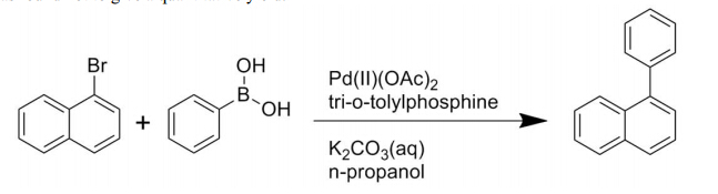
McFarlane J, Luo H, Garland M, et al. (2010) Evaluation of phenylnaphthalenes as heat transfer fluids for high temperature energy applications. Sep Sci Technol 45: 1908-1920. doi: 10.1080/01496395.2010.493800
    [27] Steele WV, Chirico RD, Knipmeyer SE, et al. (1992) The thermodynamic properties of 9-methylcarbazole and of 1,2,3,4-tetrahydro-9-methylcarbazole. J Chem Therm 24: 245-271. doi: 10.1016/S0021-9614(05)80066-7
    [28] Zalba B, Marın JM, Cabeza LF, et al. (2003) Review on thermal energy storage with phase change: materials, heat transfer analysis and applications. App Thermal Eng 23: 251-283. doi: 10.1016/S1359-4311(02)00192-8
    [29] Wilhelms A, Telnæs N, Steen A, et al. (1998) A quantitative study of aromatic hydrocarbons in a natural maturity shale sequence—the 3-methylphenanthrene/retene ratio, a pragmatic maturity parameter. Org Geochem 29: 97-105. doi: 10.1016/S0146-6380(98)00112-0
    [30] Orem WH, Tatu CA, Lerch HE, et al. (2007) Organic compounds in produced waters from coalbed natural gas wells in the Powder River Basin, Wyoming, USA. App Geochem 22: 2240-2256. doi: 10.1016/j.apgeochem.2007.04.010
    [31] Miyaura M, Yamada K, Suzuki A (1979) A new stereospecific cross-coupling by the palladium-catalyzed reaction of 1-alkenylboranes with 1-alkenyl or 1-alkynyl halides. Tet Lett 20: 3437-3440. doi: 10.1016/S0040-4039(01)95429-2
    [32] Eguchi H, Nishiyama M, Ishikawa S, et al. (2012) Development and industrialization of efficient cross-coupling reactions. J Syn Org Chem Japan 70: 937-946. doi: 10.5059/yukigoseikyokaishi.70.937
    [33] Franzen R, Xu YJ (2005) Review on green chemistry - Suzuki cross coupling in aqueous media. Can J Chem 83: 266-272. doi: 10.1139/v05-048
    [34] Narayanan R (2010) Recent advances in noble metal nanocatalysts for Suzuki and Heck cross-coupling reactions. Molecules 15: 2124-2138. doi: 10.3390/molecules15042124
    [35] Polshettiwar V, Decottignies A, Len C, et al. (2010) Suzuki-Miyaura cross-coupling reactions in aqueous media: Green and sustainable syntheses of biaryls. ChemSusChem 3: 502-522. doi: 10.1002/cssc.200900221
    [36] Seechurn C, Kitching MO, Colacot TJ, et al. (2012) Palladium-catalyzed cross-coupling: A historical contextual perspective to the 2010 Nobel prize. Angew Chem 51: 5062-5085. doi: 10.1002/anie.201107017
    [37] Colon I, Kelsey DR (1986) Coupling of aryl chlorides by nickel and reducing metals. J Org Chem 51: 2627-2637. doi: 10.1021/jo00364a002
    [38] Bell JR, Joseph RAI, McFarlane J, et al. (2012) Phenylnaphthalene as a Heat Transfer Fluid for Concentrating Solar Power: High-Temperature Static Experiments Oak Ridge, TN: Oak Ridge National Laboratory. ORNL/TM-2012/118.
    [39] Cioslowski J, Liu G, Martinov M, et al. (1996) Energetics and site specificity of the homolytic C-H bond cleavage in benzenoid hydrocarbons: An ab initio electronic structure study. J Am Chem Soc 118: 5261-5264. doi: 10.1021/ja9600439
    [40] Cioslowski J, Piskorz P, Liu G, et al. (1996) Regularities in energies and geometries of biaryls: An ab initio electronic structure study. J Phys Chem 100: 19333-19335. doi: 10.1021/jp961298b
    [41] 
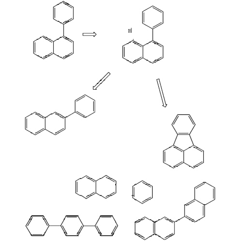
Cioslowski J, Piskorz P, Moncrieff D (1998) Thermally induced cyclodehydrogenation of biaryls: A simple radical reaction of a sequence of rearrangements? J Org Chem 63: 4051-4054. doi: 10.1021/jo980132z
    [42] Gaynor S, Greszta D, Mardare D, et al. (1994) Controlled radical polymerization. J Macromolec Sci, Part A: Pure Appl Chem 31: 1561-1578. doi: 10.1080/10601329408545868
    [43] Duran A, Carmona M, Monteagudo JM (2004) Modelling soot and SOF emissions from a diesel engine. Chemosphere 56: 209-225. doi: 10.1016/j.chemosphere.2004.03.008
    [44] Pope CJ, Marr JA, Howard JB (1993) Chemistry of fullerenes C60 and C70 formation in flames. J Phys Chem 97: 11001-11013. doi: 10.1021/j100144a018
    [45] MatLab (2012). 2012a ed. Natick, MA: Mathworks.
    [46] Hines AL, Maddox RN (1985) Mass Transfer Fundamentals and Applications. Englewood Cliffs, NJ: Prentice-Hall, Inc
    [47] Rocha MAA, Lima CFRAC, Santos LMNBF (2008) Phase transition thermodynamics of phenyl and biphenyl naphthalenes. J Chem Thermodyn 40: 1458-1463. doi: 10.1016/j.jct.2008.04.010
    [48] Turchi C (2010) Parabolic Trough Reference Plant for Cost Modeling with Solar Advisor Model (SAM). Golden, CO: National Renewable Energy Laboratory. NREL/TP-550-47605.
    [49] Curzon FL, Ahlborn B (1975) Efficiency of a Carnot engine at maximum power output. Am J Phys 43: 22-24. doi: 10.1119/1.10023
    [50] Kolb GJ, Diver RB (2008) Conceptual design of an advanced trough utilizing a molten salt working fluid. SolarPACES Symposium. Las Vegas, NV: Sandia National Laboratories, Albuquerque, NM.
    [51] Kennedy CE, Price H (2005) Progress in development of high-temperature solar-selective coating. International Solar Energy Conference. Orlando, FL: National Renewable Energy Laboratory. pp. ISEC2005-76039.
    [52] Adili A, Kerkeni C, Ben Nasralla S (2009) Estimation of thermophysical properties of fouling using inverse problem and its impact on heat transfer efficiency. Solar Energy 83: 1619-1628. doi: 10.1016/j.solener.2009.05.014
    [53] Kennedy CE, Price H (2005) Progress in Development of High-Temperature Solar-Selective Coating. Golden, CO National Renewable Energy Laboratory. NREL/CP-520-36997.
    [54] Kennedy CE (2002) Review of Mid-to-High-Temperature Solar Selective Absorber Materials. Golden, CO National Renewable Energy Laboratory. NREL/TP-520-31267.
  • This article has been cited by:

    1. Mangesh Sakhalkar, Sharad V. Lande, Sudeshna Chandra, Facile and Selective Mono Benzylation of Naphthalene Using Atom Efficient Chloroaluminate Ionic Liquid, 2020, 1040-6638, 1, 10.1080/10406638.2020.1802304
    2. Sarah Holliday, Christine K. Luscombe, Low Boiling Point Solvent Additives for Improved Photooxidative Stability in Organic Photovoltaics, 2018, 4, 2199160X, 1700416, 10.1002/aelm.201700416
  • Reader Comments
  • © 2014 the Author(s), licensee AIMS Press. This is an open access article distributed under the terms of the Creative Commons Attribution License (http://creativecommons.org/licenses/by/4.0)
通讯作者: 陈斌, bchen63@163.com
  • 1. 

    沈阳化工大学材料科学与工程学院 沈阳 110142

  1. 本站搜索
  2. 百度学术搜索
  3. 万方数据库搜索
  4. CNKI搜索

Metrics

Article views(7314) PDF downloads(1302) Cited by(2)

Article outline

Figures and Tables

Figures(14)  /  Tables(9)

/

DownLoad:  Full-Size Img  PowerPoint
Return
Return

Catalog