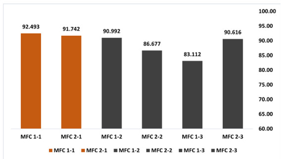
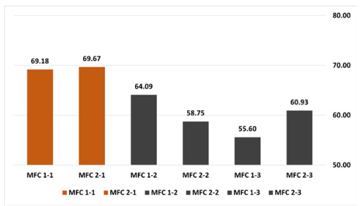
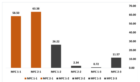
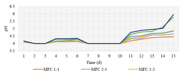
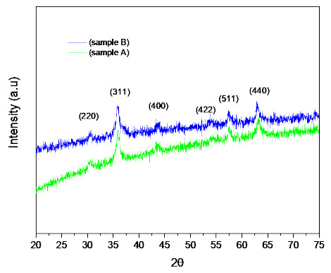
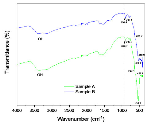
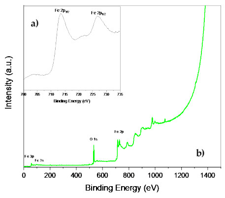
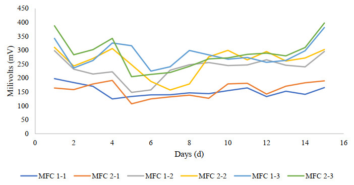
Microbial fuel cells (MFCs) are devices that use microorganisms to produce electricity from organic matter. In this study, the bacterium Delftia acidovorans spp was used to evaluate energy generation in a single-chamber MFC. In this evaluation, six MFCs were assembled with different exchange membranes: two with carbon fiber composite membrane, two with maghemite membrane and two with heat-treated maghemite. Synthetic maghemite was characterized using X-ray powder diffraction (XRD), X-ray photoelectron spectroscopy (XPS), Brunauer-Emmett-Teller (BET) and Fourier transform infrared spectroscopy (FTIR) measurements. Bioelectricity monitoring in the MFCs was conducted for 15 days, with data collected every 60 seconds. The cell that achieved the highest bioelectricity production was the one with heat-treated maghemite, reaching a production of 286.50mV. It used 100% leachate from fruit and vegetable waste as a substrate, starting with values of 365 mg/L of N-NH4, 96000 mg/L of biochemical oxygen demand (BOD5), 101500 mg/L of chemical oxygen demand (COD) and a pH of 4.11. In the results, the carbon fiber treatment had a higher removal efficiency percentage of up to 63.38% for BOD5 and 69.67% for COD. For ammonium nitrogen removal, all cells showed good removal efficiency of up to 92.49%. The pH value increased in all treatments due to the degradation of organic matter, reaching a value of up to 5.96. Thus, the efficiency of Delftia acidovorans spp. and carbon fiber are a good alternative as an exchange membrane in purifying leachate contaminants within an MFC.
Citation: Cristina Calderón-Tapia, Daniel Chuquín-Vasco, Alex Guambo-Galarza, Soledad Núñez-Moreno, Cristina Silva-Cisneros. Bioelectricity production from anaerobically treated leachate in microbial fuel cell using Delftia acidovorans spp.[J]. AIMS Environmental Science, 2023, 10(6): 847-867. doi: 10.3934/environsci.2023046
Microbial fuel cells (MFCs) are devices that use microorganisms to produce electricity from organic matter. In this study, the bacterium Delftia acidovorans spp was used to evaluate energy generation in a single-chamber MFC. In this evaluation, six MFCs were assembled with different exchange membranes: two with carbon fiber composite membrane, two with maghemite membrane and two with heat-treated maghemite. Synthetic maghemite was characterized using X-ray powder diffraction (XRD), X-ray photoelectron spectroscopy (XPS), Brunauer-Emmett-Teller (BET) and Fourier transform infrared spectroscopy (FTIR) measurements. Bioelectricity monitoring in the MFCs was conducted for 15 days, with data collected every 60 seconds. The cell that achieved the highest bioelectricity production was the one with heat-treated maghemite, reaching a production of 286.50mV. It used 100% leachate from fruit and vegetable waste as a substrate, starting with values of 365 mg/L of N-NH4, 96000 mg/L of biochemical oxygen demand (BOD5), 101500 mg/L of chemical oxygen demand (COD) and a pH of 4.11. In the results, the carbon fiber treatment had a higher removal efficiency percentage of up to 63.38% for BOD5 and 69.67% for COD. For ammonium nitrogen removal, all cells showed good removal efficiency of up to 92.49%. The pH value increased in all treatments due to the degradation of organic matter, reaching a value of up to 5.96. Thus, the efficiency of Delftia acidovorans spp. and carbon fiber are a good alternative as an exchange membrane in purifying leachate contaminants within an MFC.

| [1] |
Hersh B, Mirkouei A, Sessions J, et al. (2019) A Review and Future Directions on Enhancing Sustainability Benefits across Food-Energy-Water Systems: The Potential Role of Biochar-Derived Products. AIMS Environ Sci 6: 379–416. https://doi.org/10.3934/environsci.2019.5.379 doi: 10.3934/environsci.2019.5.379

|
| [2] |
Yang X, Chen S. (2021) Microorganisms in Sediment Microbial Fuel Cells: Ecological Niche, Microbial Response, and Environmental Function. Sci. Total Environ 756: 144145. https://doi.org/10.1016/j.scitotenv.2020.144145 doi: 10.1016/j.scitotenv.2020.144145
|
| [3] |
Miramontes-Viña V, Romero-Castro N, López-Cabarcos M Á. (2023) Advancing towards a Sustainable Energy Model. Uncovering the Untapped Potential of Rural Areas. AIMS Environ Sci 10: 287–312. https://doi.org/10.3934/environsci.2023017 doi: 10.3934/environsci.2023017
|
| [4] |
Srivastava R K, Boddula R, Pothu R. (2022) Microbial Fuel Cells: Technologically Advanced Devices and Approach for Sustainable/Renewable Energy Development. Energy Convers Manag X: 13: 100160. https://doi.org/10.1016/j.ecmx.2021.100160 doi: 10.1016/j.ecmx.2021.100160
|
| [5] |
Darmawan R, Juliastuti S R, Hendrianie N, et al. (2022) Effect of Electrode Modification on the Production of Electrical Energy and Degradation of Cr (Ⅵ) Waste Using Tubular Microbial Fuel Cell. AIMS Environ Sci 9: 505–525. https://doi.org/10.3934/environsci.2022030 doi: 10.3934/environsci.2022030
|
| [6] |
Xin S, Shen J, Liu G, et al. (2022) Electricity Generation and Microbial Community of Single-Chamber Microbial Fuel Cells in Response to Cu2O Nanoparticles/Reduced Graphene Oxide as Cathode Catalyst. Chem Eng J 380: 122446. https://doi.org/10.1016/j.cej.2019.122446 doi: 10.1016/j.cej.2019.122446
|
| [7] |
Pant D, Van Bogaert G, Diels L, et al. (2010) A Review of the Substrates Used in Microbial Fuel Cells (MFCs) for Sustainable Energy Production. Bioresour. Technol 101: 1533–1543. https://doi.org/10.1016/j.biortech.2009.10.017 doi: 10.1016/j.biortech.2009.10.017
|
| [8] |
Guambo A, Calderón C, Paña S, et al. (2021) Bioelectricity Production with Organic Substrates, Nitrates and Lead Using High Andean Soils. Adv Intell Syst Comput 1277: 198–208. https://doi.org/10.1007/978-3-030-60467-7_17 doi: 10.1007/978-3-030-60467-7_17
|
| [9] |
Arulmani S R B, Gnanamuthu H L, Kandasamy S, et al. (2021) Sustainable Bioelectricity Production from Amaranthus Viridis and Triticum Aestivum Mediated Plant Microbial Fuel Cells with Efficient Electrogenic Bacteria Selections. Process Biochem 107. https://doi.org/10.1016/j.procbio.2021.04.015 doi: 10.1016/j.procbio.2021.04.015
|
| [10] |
Nguyen H D, Babel S. (2023) A Novel Coupled Microbial Fuel Cell Operation for Organic and Nitrogen Removal with Simultaneous Energy Recovery from Wastewater. Sustain Energy Technol Assessments 55: 102981. https://doi.org/10.1016/j.seta.2022.102981 doi: 10.1016/j.seta.2022.102981
|
| [11] |
Bajracharya S. (2020) Microbial Fuel Cell Coupled with Anaerobic Treatment Processes for Wastewater Treatment. Integr Microb Fuel Cells Wastewater Treat 295–311. ttps://doi.org/10.1016/B978-0-12-817493-7.00014-X doi: 10.1016/B978-0-12-817493-7.00014-X
|
| [12] |
Wrighton K C, Agbo P, Warnecke F, et al. (2008) A Novel Ecological Role of the Firmicutes Identified in Thermophilic Microbial Fuel Cells. ISME J 2: 1146–1156. https://doi.org/10.1038/ismej.2008.48 doi: 10.1038/ismej.2008.48
|
| [13] |
Zhang G, Feng S, Jiao Y, et al. (2017) Cathodic Reducing Bacteria of Dual-Chambered Microbial Fuel Cell. Int J Hydrogen Energy 42: 27607–27617. https://doi.org/10.1016/j.ijhydene.2017.06.095 doi: 10.1016/j.ijhydene.2017.06.095
|
| [14] |
Zhang G, Zhao Q, Jiao Y, et al. (2012) Biocathode Microbial Fuel Cell for Efficient Electricity Recovery from Dairy Manure. Biosens Bioelectron 31. https://doi.org/10.1016/j.bios.2011.11.036 doi: 10.1016/j.bios.2011.11.036
|
| [15] |
Chen C Y, Chen T Y, Chung Y C A (2014) Comparison of Bioelectricity in Microbial Fuel Cells with Aerobic and Anaerobic Anodes. Environ Technol 35. https://doi.org/10.1080/09593330.2013.826254 doi: 10.1080/09593330.2013.826254
|
| [16] |
Erensoy A, Mulayim S, Orhan A, et al. (2022) The System Design of the Peat-Based Microbial Fuel Cell as a New Renewable Energy Source: The Potential and Limitations. Alexandria Eng J 61: 8743–8750. https://doi.org/10.1016/j.aej.2022.02.020 doi: 10.1016/j.aej.2022.02.020
|
| [17] |
Szydlowski L, Lan T C T, Shibata N, et al. (2020) Metabolic Engineering of a Novel Strain of Electrogenic Bacterium Arcobacter Butzleri to Create a Platform for Single Analyte Detection Using a Microbial Fuel Cell. Enzyme Microb Technol 139: 109564. https://doi.org/10.1016/j.enzmictec.2020.109564 doi: 10.1016/j.enzmictec.2020.109564
|
| [18] |
Krithika T, Kavitha R, Dinesh M, et al. (2021) Assessment of Ligninolytic Bacterial Consortium for the Degradation of Azo Dye with Electricity Generation in a Dual-Chambered Microbial Fuel Cell. Environ Challenges 4: 100093. https://doi.org/10.1016/j.envc.2021.100093 doi: 10.1016/j.envc.2021.100093
|
| [19] |
Gupta P, Pandey K, Verma N. (2021) Improved Oxygen Reduction and Simultaneous Glyphosate Degradation over Iron Phthalocyanine and Reduced Graphene Oxide‒dispersed Activated Carbon Fiber Electrodes in a Microbial Fuel Cell. J Power Sources 514. https://doi.org/10.1016/j.jpowsour.2021.230592 doi: 10.1016/j.jpowsour.2021.230592
|
| [20] |
Ambaye T G, Vaccari M, Franzetti A, et al. (2023) Microbial Electrochemical Bioremediation of Petroleum Hydrocarbons (PHCs) Pollution: Recent Advances and Outlook. Chem Eng J 452. https://doi.org/10.1016/j.cej.2022.139372 doi: 10.1016/j.cej.2022.139372
|
| [21] |
Fatehbasharzad P, Aliasghari S, Tabrizi I S, et al. (2022) Microbial Fuel Cell Applications for Removal of Petroleum Hydrocarbon Pollutants: A Review. Water Resour Ind 28: 100178. https://doi.org/10.1016/j.wri.2022.100178 doi: 10.1016/j.wri.2022.100178
|
| [22] |
Puig S, Serra M, Coma M, et al. (2011) Microbial Fuel Cell Application in Landfill Leachate Treatment. J Hazard Mater 185. https://doi.org/10.1016/j.jhazmat.2010.09.086 doi: 10.1016/j.jhazmat.2010.09.086
|
| [23] |
Biffinger J C, Pietron J, Ray R, et al. (2007) A Biofilm Enhanced Miniature Microbial Fuel Cell Using Shewanella Oneidensis DSP10 and Oxygen Reduction Cathodes. Biosens Bioelectron 22: 1672–1679. https://doi.org/10.1016/j.bios.2006.07.027 doi: 10.1016/j.bios.2006.07.027
|
| [24] |
Pu K B, Li T T, Gao J Y, et al. (2022) Floating Flexible Microbial Fuel Cells for Electricity Generation and Municipal Wastewater Treatment. Sep Purif Technol 300. https://doi.org/10.1016/j.seppur.2022.121915 doi: 10.1016/j.seppur.2022.121915
|
| [25] |
Ghangrekar M M, Shinde V B. (2007) Performance of Membrane-Less Microbial Fuel Cell Treating Wastewater and Effect of Electrode Distance and Area on Electricity Production. Bioresour Technol 98: 2879–2885. https://doi.org/10.1016/j.biortech.2006.09.050 doi: 10.1016/j.biortech.2006.09.050
|
| [26] |
Xu J, Sheng G P, Luo H W, et al. (2012) Fouling of Proton Exchange Membrane (PEM) Deteriorates the Performance of Microbial Fuel Cell. Water Res 46: 1817–1824. https://doi.org/10.1016/j.watres.2011.12.060 doi: 10.1016/j.watres.2011.12.060
|
| [27] |
Kondaveeti S, Lee J, Kakarla R, et al. (2014) Low-Cost Separators for Enhanced Power Production and Field Application of Microbial Fuel Cells (MFCs). Electrochim Acta 132: 434–440. https://doi.org/10.1016/j.electacta.2014.03.046 doi: 10.1016/j.electacta.2014.03.046
|
| [28] |
Li D, Feng Y, Li F, et al. (2023) Carbon Fibers for Bioelectrochemical: Precursors, Bioelectrochemical System, and Biosensors. Adv Fiber Mater 5: 699–730. https://doi.org/10.1007/s42765-023-00256-w doi: 10.1007/s42765-023-00256-w
|
| [29] |
Shirvanimoghaddam K, Hamim S U, Akbari M K, et al. (2017) Carbon Fiber Reinforced Metal Matrix Composites: Fabrication Processes and Properties. Compos. Part A Appl Sci Manuf 92: 70–96. https://doi.org/10.1016/j.compositesa.2016.10.032 doi: 10.1016/j.compositesa.2016.10.032
|
| [30] |
Oroumei A, Naebe M. (2017) Mechanical Property Optimization of Wet-Spun Lignin/Polyacrylonitrile Carbon Fiber Precursor by Response Surface Methodology. Fibers Polym 18. https://doi.org/10.1007/s12221-017-7363-9 doi: 10.1007/s12221-017-7363-9
|
| [31] |
Djellali M, Kameche M, Kebaili H, et al. (2021) Synthesis of Nickel-Based Layered Double Hydroxide (LDH) and Their Adsorption on Carbon Felt Fibres: Application as Low Cost Cathode Catalyst in Microbial Fuel Cell (MFC). Environ Technol 42. https://doi.org/10.1080/09593330.2019.1635652 doi: 10.1080/09593330.2019.1635652
|
| [32] |
Li X, Liu G, Ma F, et al. (2018) Enhanced Power Generation in a Single-Chamber Dynamic Membrane Microbial Fuel Cell Using a Nonstructural Air-Breathing Activated Carbon Fiber Felt Cathode. Energy Convers Manag 172. https://doi.org/10.1016/j.enconman.2018.07.011 doi: 10.1016/j.enconman.2018.07.011
|
| [33] |
Jiang D, Chen H, Xie H, et al. (2023) Fe, N, S Co-Doped Cellulose Paper Carbon Fibers as an Air-Cathode Catalyst for Microbial Fuel Cells. Environ Res 221. https://doi.org/10.1016/j.envres.2023.115308 doi: 10.1016/j.envres.2023.115308
|
| [34] |
Yan S, Xiong W, Xing S, et al. (2017) Oxidation of Organic Contaminant in a Self-Driven Electro/Natural Maghemite/Peroxydisulfate System: Efficiency and Mechanism. Sci Total Environ 599–600. https://doi.org/10.1016/j.scitotenv.2017.05.037 doi: 10.1016/j.scitotenv.2017.05.037
|
| [35] |
Khalifa A Y Z, Almalki M. (2019) Polyphasic Characterization of Delftia Acidovorans ESM-1, a Facultative Methylotrophic Bacterium Isolated from Rhizosphere of Eruca Sativa. Saudi J Biol Sci 26. https://doi.org/10.1016/j.sjbs.2018.05.015 doi: 10.1016/j.sjbs.2018.05.015
|
| [36] |
Chen Y L, Lee C C, Lin Y L, et al. (2015) Obtaining Long 16S RDNA Sequences Using Multiple Primers and Its Application on Dioxin-Containing Samples. BMC Bioinformatics 16: S13. https://doi.org/10.1186/1471-2105-16-S18-S13 doi: 10.1186/1471-2105-16-S18-S13
|
| [37] |
Geer L Y, Marchler-Bauer A, Geer R C, et al.(2009) The NCBI BioSystems Database. Nucleic Acids Res 38. https://doi.org/10.1093/nar/gkp858 doi: 10.1093/nar/gkp858
|
| [38] |
Meeker E W, Wagner E C (1933)Titration of Ammonia in Presence of Boric Acid. Ind Eng Chem Anal Ed 5: 396–398. doi: 10.1021/ac50086a012.https://doi.org/10.1021/ac50086a012 doi: 10.1021/ac50086a012
|
| [39] | Standard Methods For the Examination of Water and Wastewater 5210 BIOCHEMICAL OXYGEN DEMAND (BOD). Stand Methods Exam Water Wastewater doi: 10.2105/SMWW.2882.102. |
| [40] | Wastewater, S.M.F. the E. of W. and 5220 CHEMICAL OXYGEN DEMAND (COD). Stand. Methods Exam. Water Wastewater. |
| [41] | Wastewater, S.M.F. the E. of W. and 4500-H+ PH. Stand. Methods Exam. Water Wastewater. |
| [42] |
Zhang C F, Zhong X C, Yu H Y, et al. (2009) Effects of Cobalt Doping on the Microstructure and Magnetic Properties of Mn-Zn Ferrites Prepared by the Co-Precipitation Method. Phys B Condens Matter 404: 2327–2331. https://doi.org/10.1016/j.physb.2008.12.044 doi: 10.1016/j.physb.2008.12.044
|
| [43] |
Silva C, Borbáth I, Zelenka K, et al. (2022) Effect of the Reductive Treatment on the State and Electrocatalytic Behavior of Pt in Catalysts Supported on Ti0.8Mo0.2O2-C Composite. React Kinet Mech Catal 135: 29–47. https://doi.org/10.1007/s11144-021-02131-4 doi: 10.1007/s11144-021-02131-4
|
| [44] |
Pászti Z, Hakkel O, Keszthelyi T, et al. (2010) Interaction of Carbon Monoxide with Au(111) Modified by Ion Bombardment: A Surface Spectroscopy Study under Elevated Pressure. Langmuir 26: 16312–16324. https://doi.org/10.1021/la1014913 doi: 10.1021/la1014913
|
| [45] | N. Fairley CasaXPS: Spectrum Processing Software for XPS, AES and SIMS. Cheshiree. |
| [46] |
Diczházi D, Borbáth I, Bakos I, et al. (2021) Design of Mo-Doped Mixed Oxide–Carbon Composite Supports for Pt-Based Electrocatalysts: The Nature of the Mo-Pt Interaction. Catal Today 366: 31–40. https://doi.org/10.1016/j.cattod.2020.04.004 doi: 10.1016/j.cattod.2020.04.004
|
| [47] | Mohai, M. XPS MultiQuant: Multi-Model X-Ray Photoelectron Spectroscopy Quantification Program. Version 7.00.92. 2011. |
| [48] | Mohai, M. XPS MultiQuant: Multimodel XPS Quantification Software. Surf Interface Anal 36: 828–832. https://doi.org/10.1002/sia.1775 |
| [49] |
Zhang J, Li J, Ye D, et al. (2014) Enhanced Performances of Microbial Fuel Cells Using Surface-Modified Carbon Cloth Anodes: A Comparative Study. Int J Hydrogen Energy 39: 19148–19155. https://doi.org/10.1016/j.ijhydene.2014.09.067 doi: 10.1016/j.ijhydene.2014.09.067
|
| [50] |
Feng Y, Yang Q, Wang X, et al. (2010) Treatment of Carbon Fiber Brush Anodes for Improving Power Generation in Air–Cathode Microbial Fuel Cells. J Power Sources 195: 1841–1844. https://doi.org/10.1016/j.jpowsour.2009.10.030 doi: 10.1016/j.jpowsour.2009.10.030
|
| [51] |
Karami M, McMorrow G V, Wang L (2018) Continuous Monitoring of Indoor Environmental Quality Using an Arduino-Based Data Acquisition System. J Build Eng 19. https://doi.org/10.1016/j.jobe.2018.05.014 doi: 10.1016/j.jobe.2018.05.014
|
| [52] | Escapa A, Gil-Carrera L, García V, et al. (2012) Performance of a Continuous Flow Microbial Electrolysis Cell (MEC) Fed with Domestic Wastewater. Bioresour Technol 117. |
| [53] |
Nanda A, Mohapatra B B, Mahapatra A P K, et al. (2021) Multiple Comparison Test by Tukey's Honestly Significant Difference (HSD): Do the Confident Level Control Type I Error. Int J Stat Appl Math 6. https://doi.org/10.22271/maths.2021.v6.i1a.636 doi: 10.22271/maths.2021.v6.i1a.636
|
| [54] |
Feng S, Hou S, Huang X, et al. (2019) Insights into the Microbial Community Structure of Anaerobic Digestion of Municipal Solid Waste Landfill Leachate for Methane Production by Adaptive Thermophilic Granular Sludge. Electron J Biotechnol 39. https://doi.org/10.1016/j.ejbt.2019.04.001 doi: 10.1016/j.ejbt.2019.04.001
|
| [55] |
Ghosh P, Gupta A, Thakur I S. (2015) Combined Chemical and Toxicological Evaluation of Leachate from Municipal Solid Waste Landfill Sites of Delhi, India. Environ Sci Pollut Res 22. https://doi.org/10.1007/s11356-015-4077-7 doi: 10.1007/s11356-015-4077-7
|
| [56] | MAE TULSMA Available online: https://www.ambiente.gob.ec/wp-content/uploads/downloads/2018/05/TULSMA.pdf (accessed on 2 October 2023). |
| [57] |
Saeed T, Yadav A K, Miah M J (2022) Landfill Leachate and Municipal Wastewater Co-Treatment in Microbial Fuel Cell Integrated Unsaturated and Partially Saturated Tidal Flow Constructed Wetlands. J Water Process Eng 46. https://doi.org/10.1016/j.jwpe.2022.102633 doi: 10.1016/j.jwpe.2022.102633
|
| [58] |
Kumar S S, Kumar A, Malyan S K, et al. (2023) Landfill Leachate Valorization: A Potential Alternative to Burden off Resources and Support Energy Systems. Fuel 331. https://doi.org/10.1016/j.fuel.2022.125911 doi: 10.1016/j.fuel.2022.125911
|
| [59] |
Hassan M, Wei H, Qiu H, et al. (2018) Power Generation and Pollutants Removal from Landfill Leachate in Microbial Fuel Cell: Variation and Influence of Anodic Microbiomes. Bioresour Technol 247. https://doi.org/10.1016/j.biortech.2017.09.124 doi: 10.1016/j.biortech.2017.09.124
|
| [60] |
Li X, Lu Y, Luo H, et al. (2021) Effect of PH on Bacterial Distributions within Cathodic Biofilm of the Microbial Fuel Cell with Maltodextrin as the Substrate. Chemosphere 265. https://doi.org/10.1016/j.chemosphere.2020.129088 doi: 10.1016/j.chemosphere.2020.129088
|
| [61] |
Singh M, Ulbrich P, Prokopec V, et al. (2013) Vapour Phase Approach for Iron Oxide Nanoparticle Synthesis from Solid Precursors. J Solid State Chem 200: 150–156. https://doi.org/10.1016/j.jssc.2013.01.037 doi: 10.1016/j.jssc.2013.01.037
|
| [62] |
Asuha S, Zhao Y M, Zhao S, et al. (2012) Synthesis of Mesoporous Maghemite with High Surface Area and Its Adsorptive Properties. Solid State Sci 14: 833–839. https://doi.org/10.1016/j.solidstatesciences.2012.04.011 doi: 10.1016/j.solidstatesciences.2012.04.011
|
| [63] |
Trushkina Y, Tai C W, Salazar-Alvarez G. (2019) Fabrication of Maghemite Nanoparticles with High Surface Area. Nanomaterials 9. https://doi.org/10.3390/nano9071004 doi: 10.3390/nano9071004
|
| [64] |
Guivar J A R, Sadrollahi E, Menzel D, et al. Magnetic, Structural and Surface Properties of Functionalized Maghemite Nanoparticles for Copper and Lead Adsorption. RSC Adv 7: 28763–28779, https://doi.org/10.1039/C7RA02750H doi: 10.1039/C7RA02750H
|
| [65] |
Patekari M D, Pawar K K, Salunkhe G B, et al. (2021) Synthesis of Maghemite Nanoparticles for Highly Sensitive and Selective NO2 Sensing. Mater Sci Eng B Solid-State Mater Adv Technol 272: 115339. https://doi.org/10.1016/j.mseb.2021.115339 doi: 10.1016/j.mseb.2021.115339
|
| [66] |
Cao D, Li H, Pan L, et al. High Saturation Magnetization of γ 3-Fe2 O3 Nano-Particles by a Facile One-Step Synthesis Approach. Sci Rep 6: 1–9. https://doi.org/10.1038/srep32360 doi: 10.1038/srep32360
|
| [67] |
Shetty A R, de Gannes V, Obi C C, et al. (2015) Complete Genome Sequence of the Phenanthrene-Degrading Soil Bacterium Delftia Acidovorans Cs1-4. Stand Genomic Sci 10. https://doi.org/10.1186/s40793-015-0041-x doi: 10.1186/s40793-015-0041-x
|
| [68] |
Morel M A, Ubalde M C, Braña V, et al. (2011) Delftia Sp. JD2: A Potential Cr(Ⅵ)-Reducing Agent with Plant Growth-Promoting Activity. Arch Microbiol 193. https://doi.org/10.1007/s00203-010-0632-2 doi: 10.1007/s00203-010-0632-2
|
| [69] |
Leibeling S, Schmidt F, Jehmlich N, et al. (2010) Declining Capacity of Starving Delftia Acidovorans MC1 to Degrade Phenoxypropionate Herbicides Correlates with Oxidative Modification of the Initial Enzyme. Environ Sci Technol 44. https://doi.org/10.1021/es903619j doi: 10.1021/es903619j
|
| [70] |
Morel M A, Iriarte A, Jara Tellechea E S, et al. (2016) Revealing the Biotechnological Potential of Delftia Sp. JD2 by a Genomic Approach. AIMS Bioeng 3: 156–175. https://doi.org/10.3934/bioeng.2016.2.156 doi: 10.3934/bioeng.2016.2.156
|
| [71] |
Nosek D, Samsel O, Pokój T, et al. (2023) Waste Volatile Fatty Acids as a Good Electron Donor in Microbial Fuel Cell with the Iron-Modified Anode. Int J Environ Sci Technol 20. https://doi.org/10.1007/s13762-023-04850-8 doi: 10.1007/s13762-023-04850-8
|
| [72] |
Ishii S, Logan B E, Sekiguchi Y. (2012) Enhanced Electrode-Reducing Rate during the Enrichment Process in an Air-Cathode Microbial Fuel Cell. Appl Microbiol Biotechnol 94. https://doi.org/10.1007/s00253-011-3844-8 doi: 10.1007/s00253-011-3844-8
|
| [73] |
Jangir Y, French S, Momper L M, et al. (2016) Isolation and Characterization of Electrochemically Active Subsurface Delftia and Azonexus Species. Front Microbiol 7. https://doi.org/10.3389/fmicb.2016.00756 doi: 10.3389/fmicb.2016.00756
|
| [74] |
Malyan S K, Kumar S S, Fagodiya R K, et al. (2021) Biochar for Environmental Sustainability in the Energy-Water-Agroecosystem Nexus. Renew. Sustain. Energy Rev 149: 111379. https://doi.org/10.1016/j.rser.2021.111379 doi: 10.1016/j.rser.2021.111379
|
| [75] |
Saeed T, Miah M J, Yadav A K (2022) Development of Electrodes Integrated Hybrid Constructed Wetlands Using Organic, Construction, and Rejected Materials as Filter Media: Landfill Leachate Treatment. Chemosphere 303. https://doi.org/10.1016/j.chemosphere.2022.135273 doi: 10.1016/j.chemosphere.2022.135273
|
| [76] |
Vu M T, Noori M T, Min B. (2020) Magnetite/Zeolite Nanocomposite-Modified Cathode for Enhancing Methane Generation in Microbial Electrochemical Systems. Chem Eng J 393. https://doi.org/10.1016/j.cej.2020.124613 doi: 10.1016/j.cej.2020.124613
|
| [77] |
Omidi M, Mashkour M, Biswas J K, et al. (2021) From Electricity to Products: Recent Updates on Microbial Electrosynthesis (MES). Top Catal https://doi.org/10.1007/s11244-021-01503-3 doi: 10.1007/s11244-021-01503-3
|
| [78] |
Liu P, Liang P, Jiang Y, et al. (2018) Stimulated Electron Transfer inside Electroactive Biofilm by Magnetite for Increased Performance Microbial Fuel Cell. Appl Energy 216. https://doi.org/10.1016/j.apenergy.2018.01.073 doi: 10.1016/j.apenergy.2018.01.073
|
| [79] |
Nouri P, Najafpour Darzi G. (2017) Impacts of Process Parameters Optimization on the Performance of the Annular Single Chamber Microbial Fuel Cell in Wastewater Treatment. Eng Life Sci 17 https://doi.org/10.1002/elsc.201600173 doi: 10.1002/elsc.201600173
|
Figures(9) / Tables(4)

Cristina Calderón-Tapia, Daniel Chuquín-Vasco, Alex Guambo-Galarza, Soledad Núñez-Moreno, Cristina Silva-Cisneros. Bioelectricity production from anaerobically treated leachate in microbial fuel cell using Delftia acidovorans spp.[J]. AIMS Environmental Science, 2023, 10(6): 847-867. doi: 10.3934/environsci.2023046


 DownLoad: