The status of current advances in modifying surfaces for the protection of materials is reviewed in this research. The main goal of material selection is to improve and reinforce surface functionalities. A few examples of surface modification techniques include sol-gel, cladding, electroplating, plasma and thermal spraying, physical deposition of vapors (PVD), vapor chemical deposition (CVD) and beam electron physical vapor deposition (EB-PVD). Strengthening by flame, induction, laser or electron beam is one type of surface modification procedure. Other types include plasma-immersed ion implantation and ion implantation at high energies, as well as diffusion treatments like carburizing and nitriding. Friction control, improved surface corrosion and wear resistance and changes to a component's mechanical or physical qualities are all possible using surface modification methods. The study also contains contemporary research in laser therapy, PVD, EB-PVD, thermal spraying and ion implantation. Additionally, magnetron sputtering (MS) is a widely used and successful approach for thin film coating in the current study. It is crucial to remember that each approach has a distinct set of restrictions, and the method's parameters might change based on the one that is selected, such as deposition targets, overall vacuum substrate temperature, reactive or mixed gas type, pressure percentage and bias voltage, which all have impacts on the PVD technique's layer qualities. Phase formation, change in phase, hardness and film structure of monolayer and multilayer films formed on the substrate under various circumstances also cause variations in the characteristics. Additionally, ion implantation enhances the surface characteristics of layers by implanting ions such as N+, B+, C+, etc. The study shows that the higher layers of multilayer enhance the degree of hardness and lower friction coefficients. To enhance the protection of thermal resistance, a thermal spraying barrier coating was coated on substrate nickel-base alloys, and the surface materials' texture, hardness and wear rate were altered by laser beam. Additionally, a heat pipe's performance was improved by a factor of 300 by adding a tiny coating of gold.
Citation: G. A. El-Awadi. Review of effective techniques for surface engineering material modification for a variety of applications[J]. AIMS Materials Science, 2023, 10(4): 652-692. doi: 10.3934/matersci.2023037
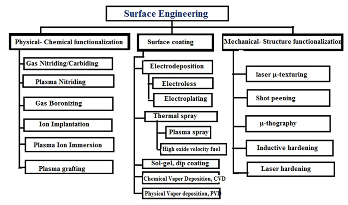
The status of current advances in modifying surfaces for the protection of materials is reviewed in this research. The main goal of material selection is to improve and reinforce surface functionalities. A few examples of surface modification techniques include sol-gel, cladding, electroplating, plasma and thermal spraying, physical deposition of vapors (PVD), vapor chemical deposition (CVD) and beam electron physical vapor deposition (EB-PVD). Strengthening by flame, induction, laser or electron beam is one type of surface modification procedure. Other types include plasma-immersed ion implantation and ion implantation at high energies, as well as diffusion treatments like carburizing and nitriding. Friction control, improved surface corrosion and wear resistance and changes to a component's mechanical or physical qualities are all possible using surface modification methods. The study also contains contemporary research in laser therapy, PVD, EB-PVD, thermal spraying and ion implantation. Additionally, magnetron sputtering (MS) is a widely used and successful approach for thin film coating in the current study. It is crucial to remember that each approach has a distinct set of restrictions, and the method's parameters might change based on the one that is selected, such as deposition targets, overall vacuum substrate temperature, reactive or mixed gas type, pressure percentage and bias voltage, which all have impacts on the PVD technique's layer qualities. Phase formation, change in phase, hardness and film structure of monolayer and multilayer films formed on the substrate under various circumstances also cause variations in the characteristics. Additionally, ion implantation enhances the surface characteristics of layers by implanting ions such as N+, B+, C+, etc. The study shows that the higher layers of multilayer enhance the degree of hardness and lower friction coefficients. To enhance the protection of thermal resistance, a thermal spraying barrier coating was coated on substrate nickel-base alloys, and the surface materials' texture, hardness and wear rate were altered by laser beam. Additionally, a heat pipe's performance was improved by a factor of 300 by adding a tiny coating of gold.

| [1] |
Barshilia HC, Selvakumar N, Rajam KS, et al. (2008) Deposition and characterization of TiAlN/TiAlON/Si3N4 tandem absorbers prepared using reactive direct current magnetron sputtering. Thin Solid Films 516: 6071–6078. https://doi.org/10.1016/j.tsf.2007.10.113 doi: 10.1016/j.tsf.2007.10.113

|
| [2] | Matthews A, Rickerby DS (1991) Advanced Surface Coatings: A Handbook of Surface Engineering, New York: Springer Dordrecht. |
| [3] |
Setiawan T, Abidin Z, Hendra C (2021) Making prototype of electro plating equipment for home industryome industri. JITTER 8: 145–149. https://doi.org/10.33197/jitter.vol8.iss1.2021.735 doi: 10.33197/jitter.vol8.iss1.2021.735
|
| [4] | Prathap P, Riyaz SM, Sai GM, et al. (2020) Experimental investigation of chromium and nickel thin sheets on EN8 steel by plating technique. IJSRED 4: 509–516. Available from: www.ijsred.com/volume3/issue2/IJSRED-V3I2P77.pdf. |
| [5] | Zhang WH, Fei JY, Luo LL, et al. (2013) High speed pulse electro plating process of nickel. J Chin Soc Corros Prot 33: 317–324. https://www.jcscp.org/EN/Y2013/V33/I4/317 |
| [6] |
Choquette Y, Menard H, Brossard L (1990) Electrocatalytic performance of composite-coated electrodes for alkaline water electrolysis. Int J Hydrogen Energy 15: 21–26. https://doi.org/10.1016/0360-3199(90)90126-J doi: 10.1016/0360-3199(90)90126-J
|
| [7] | Bunshah RF, Weissmantel C (2001) Handbook of Hard Coatings: Deposition Technologies, Properties and Applications, Park Ridge NJ: Noyes Publications. |
| [8] |
Dogan H, Findik F, Morgul O (2002) Friction and wear behaviour of implanted AISI 316L SS and comparison with a substrate. Mater Design 23: 605–610. https://doi.org/10.1016/S0261-3069(02)00066-3 doi: 10.1016/S0261-3069(02)00066-3
|
| [9] | El-Awadi GA, Abdel-Samad S, Waheed AF (2013) Characterization and properties of TiAlC layer on hard metal substrate WC/Co deposited by physical vapor deposition. Arab J Nucl Sci Appl 46: 195–202. |
| [10] |
Dogan H, Findik F, Morgul O (2002) Friction and wear behaviour of implanted AISI 316L SS and comparison with a substrate. Mater Design 23: 605–610. https://doi.org/10.1016/S0261-3069(02)00066-3 doi: 10.1016/S0261-3069(02)00066-3
|
| [11] | Creighton JR, Ho P (2001) Introduction to chemical vapor deposition (CVD), In: Xu YD, Yan XT, Chemical Vapour Deposition, London: Springer London. |
| [12] |
Selvakumar N, Barshilia HC (2012) Review of physical vapor deposited (PVD) spectrally selective coatings for mid-and high-temperature solar thermal applications. Sol Energ Mat Sol C 98: 1–23. https://doi.org/10.1016/j.solmat.2011.10.028 doi: 10.1016/j.solmat.2011.10.028
|
| [13] | Popok V, Campbell EEB (2006) Beams of atomic clusters: Effects on impact with solids. Rev Adv Mater Sci 11: 19–45. |
| [14] |
Stappen MV, Stals LM, Kerkhofs M, et al. (1995) State of the art for the industrial use of ceramic PVD coatings. Surf Coat Tech 74–75: 629–633. https://doi.org/10.1016/0257-8972(95)08296-4 doi: 10.1016/0257-8972(95)08296-4
|
| [15] | Azam RM (2017) The Study of Chromium Nitride Coating by Asymmetric Bipolar Pulsed DC Reactive Magnetron Sputtering, Lappeenranta: Lappeenranta University of Technology. |
| [16] |
Thilakan P, Minarini C, Loreti S, et al. (2001) Investigations on the crystallisation properties of RF magnetron sputtered indium tin oxide thin films. Thin Solid Films 388: 34–40. https://doi.org/10.1016/S0040-6090(01)00820-3 doi: 10.1016/S0040-6090(01)00820-3
|
| [17] |
Freller H, Haessler H (1988) Evaluation of existing ion plating processes for the deposition of multicomponent hard coatings. Surf Coat Tech 36: 219–232. https://doi.org/10.1016/0257-8972(88)90152-1 doi: 10.1016/0257-8972(88)90152-1
|
| [18] |
Ko J, Kim JW, Min HW, et al. (2022) Review of manufacturing technologies for coated accident tolerant fuel cladding. J Nucl Mater 561: 153562. https://doi.org/10.1016/j.jnucmat.2022.153562 doi: 10.1016/j.jnucmat.2022.153562
|
| [19] |
Bouzakis KD, Michailidis N, Skordaris G, et al. (2012) Cutting with coated tools: Coating technologies, characterization methods and performance optimization. CIRP Ann 61: 703–723. https://doi.org/10.1016/j.cirp.2012.05.006 doi: 10.1016/j.cirp.2012.05.006
|
| [20] |
Soum-Glaude A, Le Gal A, Bichotte M, et al. (2017) Optical characterization of TiAlNx/TiAlNy/Al2O3 tandem solar selective absorber coatings. Sol Energ Mat Sol C 170: 254–262. https://doi.org/10.1016/j.solmat.2017.06.007 doi: 10.1016/j.solmat.2017.06.007
|
| [21] | Rudnev V, Loveless D, Cook RL (2017) Handbook of Induction Heating, Boca Raton: CRC press. |
| [22] | Heimann RB (2008) Plasma-Spray Coating: Principles and Applications, Weinheim: John Wiley & Sons. |
| [23] |
Herman H, Sampath S, McCune R (2000) Thermal spray: Current status and future trends. MRS Bull 25: 17–25. https://doi.org/10.1557/mrs2000.119 doi: 10.1557/mrs2000.119
|
| [24] |
Deshpande S, Sampath S, Zhang H (2006) Mechanisms of oxidation and its role in microstructural evolution of metallic thermal spray coatings—Case study for Ni–Al. Surf Coat Tech 200: 5395–5406. https://doi.org/10.1016/j.surfcoat.2005.07.072 doi: 10.1016/j.surfcoat.2005.07.072
|
| [25] |
Jordan EH, Jiang C, Gell M (2015) The solution precursor plasma spray (SPPS) process: A review with energy considerations. J Therm Spray Techn 24: 1153–1165. https://doi.org/10.1007/s11666-015-0272-9 doi: 10.1007/s11666-015-0272-9
|
| [26] |
Jansson U, Lewin E, Rasander M, et al. (2011) Design of carbide-based nanocomposite thin films by selective alloying. Surf Coat Tech 206: 583–590. https://doi.org/10.1016/j.surfcoat.2010.06.017 doi: 10.1016/j.surfcoat.2010.06.017
|
| [27] | Strnad G, Buhagiar J (2010) Latest developments in PVD coatings for tooling. AMSET 7: 32–37. |
| [28] | Fuentes GG (2010) Surface engineering and micro-manufacturing, In: Qin Y, Micromanufacturing Engineering and Technology, Boston: William Andrew Publishing. |
| [29] |
Harris SG, Doyle ED, Wong YC, et al. (2004) Reducing the macroparticle content of cathodic arc evaporated TiN coatings. Surf Coat Tech 183: 283–294. https://doi.org/10.1016/j.surfcoat.2003.08.086 doi: 10.1016/j.surfcoat.2003.08.086
|
| [30] |
Jansson U, Lewin E (2013) Sputter deposition of transition-metal carbide films—A critical review from a chemical perspective. Thin Solid Films 536: 1–24. https://doi.org/10.1016/j.tsf.2013.02.019 doi: 10.1016/j.tsf.2013.02.019
|
| [31] |
Hoche H, Groß S, Oechsner M (2014) Development of new PVD coatings for magnesium alloys with improved corrosion properties. Surf Coat Tech 259: 102–108. https://doi.org/10.1016/j.surfcoat.2014.04.038 doi: 10.1016/j.surfcoat.2014.04.038
|
| [32] |
Kuroda S (1998) Properties and characterization of thermal sprayed coatings and a review of recent research progress. ITSC 1998: 539–550. https://doi.org/10.31399/asm.cp.itsc1998p0539 doi: 10.31399/asm.cp.itsc1998p0539
|
| [33] |
Ang ASM, Sanpo N, Sesso ML, et al. (2013) Thermal spray maps: Material genomics of processing technologies. J Therm Spray Techn 22: 1170–1183. https://doi.org/10.1007/s11666-013-9970-3 doi: 10.1007/s11666-013-9970-3
|
| [34] |
Vetter J, Barbezat G, Crummenauer J, et al. (2005) Surface treatment selections for automotive applications. Surf Coat Tech 200: 1962–1968. https://doi.org/10.1016/j.surfcoat.2005.08.011 doi: 10.1016/j.surfcoat.2005.08.011
|
| [35] |
Jagadeeshanayaka N, Awasthi S, Jambagi SC, et al. (2022) Bioactive surface modifications through thermally sprayed hydroxyapatite composite coatings: A review over selective reinforcements. Biomate Sci 10: 2484–2523. https://doi.org/10.1039/D2BM00039C doi: 10.1039/D2BM00039C
|
| [36] |
Amanov A (2019) Wear resistance and adhesive failure of thermal spray ceramic coatings deposited onto graphite in response to ultrasonic nanocrystal surface modification technique. Appl Surf Sci 477: 184–197. https://doi.org/10.1016/j.apsusc.2017.11.013 doi: 10.1016/j.apsusc.2017.11.013
|
| [37] |
Fu Y, Wei J, Batchelor AW (2000) Some considerations on the mitigation of fretting damage by the application of surface-modification technologies. J Mater Process Tech 99: 231–245. https://doi.org/10.1016/S0924-0136(99)00429-X doi: 10.1016/S0924-0136(99)00429-X
|
| [38] |
Guemmaz M, Mosser A, Grob JJ, et al. (1996) Composition and structure of titanium carbonitride thin film synthesized by ion implantation. Surf Coat Tech 80: 53–56. https://doi.org/10.1016/0257-8972(95)02684-3 doi: 10.1016/0257-8972(95)02684-3
|
| [39] |
Dong H, Bell T (1999) State-of-the-art overview: Ion beam surface modification of polymers towards improving tribological properties. Surf Coat Tech 111: 29–40. https://doi.org/10.1016/S0257-8972(98)00698-7 doi: 10.1016/S0257-8972(98)00698-7
|
| [40] |
Sharma MK, Jang Y, Kim J, et al. (2014) Plasma electrolytic oxidation in surface modification of metals for electronics. JWJ 32: 241–247. https://doi.org/10.5781/JWJ.2014.32.3.27 doi: 10.5781/JWJ.2014.32.3.27
|
| [41] |
Simchen F, Sieber M, Kopp A, et al. (2020) Introduction to plasma electrolytic oxidation—An overview of the process and applications. Coatings 10: 628. https://doi.org/10.3390/coatings10070628 doi: 10.3390/coatings10070628
|
| [42] |
Makurat-Kasprolewicz B, Ossowska A (2023) Recent advances in electrochemically surface treated titanium and its alloys for biomedical applications: A review of anodic and plasma electrolytic oxidation methods. Mater Today Commun 34: 105425. https://doi.org/10.1016/j.mtcomm.2023.105425 doi: 10.1016/j.mtcomm.2023.105425
|
| [43] |
Sikdar S, Menezes PV, Maccione R, et al. (2021) Plasma electrolytic oxidation (PEO) process—Processing, properties, and applications. Nanomaterials 11: 1375. https://doi.org/10.3390/nano11061375 doi: 10.3390/nano11061375
|
| [44] | Abdulla T (2013) The Effect of Pulsed Bipolar Plasma Electrolytic Oxidation Coatings on the Mechanical Properties of Open Cell Aluminium Foams, Sheffield: University of Sheffield. |
| [45] |
Kaseem M, Fatimah S, Nashrah N, et al. (2021) Recent progress in surface modification of metals coated by plasma electrolytic oxidation: Principle, structure, and performance. Prog Mater Sci 117: 100735. https://doi.org/10.1016/j.pmatsci.2020.100735 doi: 10.1016/j.pmatsci.2020.100735
|
| [46] | Walsh FC, Low CTJ, Wood RJK, et al. (2009) Plasma electrolytic oxidation (PEO) for production of anodised coatings on lightweight metal (Al, Mg, Ti) alloys. Trans IMF 87: 122–135. https://www.tandfonline.com/doi/abs/10.1179/174591908X372482 |
| [47] |
Kaseem M, Choe HC (2021) Simultaneous improvement of corrosion resistance and bioactivity of a titanium alloy via wet and dry plasma treatments. J Alloy Compd 851: 156840. https://doi.org/10.1016/j.jallcom.2020.156840 doi: 10.1016/j.jallcom.2020.156840
|
| [48] |
Kaseem M, Hussain T, Rehman ZU, et al. (2021) Stabilization of AZ31 Mg alloy in sea water via dual incorporation of MgO and WO3 during micro-arc oxidation. J Alloy Compd 853: 157036. https://doi.org/10.1016/j.jallcom.2020.157036 doi: 10.1016/j.jallcom.2020.157036
|
| [49] |
Hussain T, Kaseem M, Ko YG (2020) Hard acid–hard base interactions responsible for densification of alumina layer for superior electrochemical performance. Corros Sci 170: 108663. https://doi.org/10.1016/j.corsci.2020.108663 doi: 10.1016/j.corsci.2020.108663
|
| [50] |
Kaseem M, Hussain T, Zeeshan UR, et al. (2021) Fabrication of functionalized coating with a unique flowery-flake structure for an effective corrosion performance and catalytic degradation. Chem Eng J 420: 129737. https://doi.org/10.1016/j.cej.2021.129737 doi: 10.1016/j.cej.2021.129737
|
| [51] |
Kim SP, Kaseem M, Choe HC (2020) Plasma electrolytic oxidation of Ti-25Nb-xTa alloys in solution containing Ca and P ions. Surf Coat Technol 395: 125916. https://doi.org/10.1016/j.surfcoat.2020.125916 doi: 10.1016/j.surfcoat.2020.125916
|
| [52] |
Qutaba S, Asmelash M, Saptaji K, et al. (2022) A review on peening processes and its effect on surfaces. Int J Adv Manuf Technol 120: 4233–4270. https://doi.org/10.1007/s00170-022-09021-6 doi: 10.1007/s00170-022-09021-6
|
| [53] |
Ye C, Zhang C, Zhao J, et al. (2021) Effects of post-processing on the surface finish, porosity, residual stresses, and fatigue performance of additive manufactured metals: A review. J Mater Eng Perform 30: 6407–6425. https://doi.org/10.1007/s11665-021-06021-7 doi: 10.1007/s11665-021-06021-7
|
| [54] | Clauer AH (1996) Laser shock peening for fatigue resistance, In: Gregory JK, Rack HJ, Eylon D, Surface Performance of Titanium, Warrendale: The Metal Society of AIME. |
| [55] | Ding K, Ye L (2006) Laser Shock Peening: Performance and Process Simulation, Cambridge: Woodhead Publishing. |
| [56] |
Sanchez AG, You C, Leering M, et al. (2021) Effects of laser shock peening on the mechanisms of fatigue short crack initiation and propagation of AA7075-T651. Int J Fatigue 143: 106025. https://doi.org/10.1016/j.ijfatigue.2020.106025 doi: 10.1016/j.ijfatigue.2020.106025
|
| [57] |
Achintha M, Nowell D, Fufari D, et al. (2014) Fatigue behaviour of geometric features subjected to laser shock peening: Experiments and modelling. Int J Fatigue 62: 171–179. https://doi.org/10.1016/j.ijfatigue.2013.04.016 doi: 10.1016/j.ijfatigue.2013.04.016
|
| [58] |
Sticchi M, Schnubel D, Kashaev N, et al. (2015) Review of residual stress modification techniques for extending the fatigue life of metallic aircraft components. Appl Mech Rev 67: 010801. https://doi.org/10.1115/1.4028160 doi: 10.1115/1.4028160
|
| [59] |
Maharjan N, Chan SY, Ramesh T, et al. (2021) Fatigue performance of laser shock peened Ti6Al4V and Al6061‐T6 alloys. Fatigue Fract Eng M 44: 733–747. https://doi.org/10.1111/ffe.13390 doi: 10.1111/ffe.13390
|
| [60] | Torkaman H (2018) Modeling and analysis of the shot peening process: A study of the residual stresses in an insert using the finite element method. Available from: https://lnu.diva-portal.org/smash/get/diva2:1241705/FULLTEXT02.pdf. |
| [61] |
Spadaro L, Hereñ ú S, Strubbia R, et al. (2020) Effects of laser shock processing and shot peening on 253 MA austenitic stainless steel and their consequences on fatigue properties. Opt Laser Technol 122: 105892. https://doi.org/10.1016/j.optlastec.2019.105892 doi: 10.1016/j.optlastec.2019.105892
|
| [62] |
Qutaba S, Asmelash M, Saptaji K, et al. (2022) A review on peening processes and its effect on surfaces. Int J Adv Manuf Technol 120: 4233–4270. https://doi.org/10.1007/s00170-022-09021-6 doi: 10.1007/s00170-022-09021-6
|
| [63] |
Van Aswegen DC, Polese C (2021) Experimental and analytical investigation of the effects of laser shock peening processing strategy on fatigue crack growth in thin 2024 aluminium alloy panels. Int J Fatigue 142: 105969. https://doi.org/10.1016/j.ijfatigue.2020.105969 doi: 10.1016/j.ijfatigue.2020.105969
|
| [64] |
Zhang X, Yang M, Zhou C, et al. (2022) A comprehensive review of fatigue behavior of laser shock peened metallic materials. Theor Appl Fract Mech 122: 103642. https://doi.org/10.1016/j.tafmec.2022.103642 doi: 10.1016/j.tafmec.2022.103642
|
| [65] |
Li G, Dong Z, Luo T, et al. (2023) Study on the influence of shot peening strengthening before shot peen forming on 2024-T351 aluminum alloy fatigue crack growth rate. Sci Rep 13: 5313. https://doi.org/10.1038/s41598-023-32616-2 doi: 10.1038/s41598-023-32616-2
|
| [66] |
Wang H, Ning C, Huang Y, et al. (2017) Improvement of abrasion resistance in artificial seawater and corrosion resistance in NaCl solution of 7075 aluminum alloy processed by laser shock peening. Opt Laser Eng 90: 179–185. https://doi.org/10.1016/j.optlaseng.2016.10.016 doi: 10.1016/j.optlaseng.2016.10.016
|
| [67] |
Tan Y, Wu G, Yang JM, et al. (2004) Laser shock peening on fatigue crack growth behaviour of aluminium alloy. Fatigue Fract Eng M 27: 649–656. https://doi.org/10.1111/j.1460-2695.2004.00763.x doi: 10.1111/j.1460-2695.2004.00763.x
|
| [68] |
Vorbau M, Hillemann L, Stintz M (2009) Method for the characterization of the abrasion induced nanoparticle release into air from surface coatings. J Aerosol Sci 40: 209–217. https://doi.org/10.1016/j.jaerosci.2008.10.006 doi: 10.1016/j.jaerosci.2008.10.006
|
| [69] | Baer DR, Thevuthasan S (2010) Characterization of thin films and coatings, In: Martin PM, Handbook of Deposition Technologies for Films and Coatings, Boston: William Andrew Publishing. |
| [70] |
Tkadletz M, Schalk N, Daniel R, et al. (2016) Advanced characterization methods for wear resistant hard coatings: A review on recent progress. Surf Coat Technol 285: 31–46. https://doi.org/10.1016/j.surfcoat.2015.11.016 doi: 10.1016/j.surfcoat.2015.11.016
|
| [71] |
Wolke JGC, van Dijk K, Schaeken HG, et al. (1994) Study of the surface characteristics of magnetron‐sputter calcium phosphate coatings. J Biomed Mater Res 28: 1477–1484. https://doi.org/10.1002/jbm.820281213 doi: 10.1002/jbm.820281213
|
| [72] |
Benmalek M, Gimenez P, Peyre JP, et al. (1991) Characterization and comparison of TiN layers deposited by different physical vapour deposition processes. Surf Coat Technol 48: 181–187. https://doi.org/10.1016/0257-8972(91)90001-D doi: 10.1016/0257-8972(91)90001-D
|
| [73] | Dearnaley G, Arps J (2006) Ion surface treatment of materials, In: Pauleau Y, Materials Surface Processing by Directed Energy Techniques, Oxford: Elsevier. |
| [74] | Ahmed MS (2013) Effect of thermal annealing and carbon implantation on the functional properties of nanocomposite TiSiN coatings on steel. Available from: https://ro.ecu.edu.au/theses/536. |
| [75] |
Zu XT, Wang ZG, Feng XD, et al. (2003) Surface characterization of a Ti-2Al-2.5Zr alloy by nitrogen ion implantation. J Alloy Compd 351: 114–118. https://doi.org/10.1016/S0925-8388(02)01094-0 doi: 10.1016/S0925-8388(02)01094-0
|
| [76] |
Takano I, Isobe S, Sasaki TA, et al. (1989) Nitrogenation of various transition metals by N2+-ion implantation. Appl Surf Sci 37: 25–32. https://doi.org/10.1016/0169-4332(89)90970-7 doi: 10.1016/0169-4332(89)90970-7
|
| [77] | Gevorkyan Е, Rucki M, Nerubatskyi VP, et al. (2022) Remanufacturing and Advanced Machining Processes for New Materials and Components, London: Taylor & Francis. |
| [78] |
Hartley NEW (1975) Ion implantation and surface modification in tribology. Wear 34: 427–438. https://doi.org/10.1016/0043-1648(75)90109-X doi: 10.1016/0043-1648(75)90109-X
|
| [79] |
Kìnig U, Wolf GK (1987) Effects of ion implantation in cemented carbides and cobalt alloys. Surf Coat Technol 33: 501–509. https://doi.org/10.1016/0257-8972(87)90214-3 doi: 10.1016/0257-8972(87)90214-3
|
| [80] |
Lu T, Qiao Y, Liu X (2012) Surface modification of biomaterials using plasma immersion ion implantation and deposition. Interface Focus 2: 325–336. https://doi.org/10.1098/rsfs.2012.0003 doi: 10.1098/rsfs.2012.0003
|
| [81] |
Belbah A, Mkaddem A, Ladaci N, et al. (2014) Low energy implantation to inhibit wear in N+ ions implanted WC-Co composite. Mater Design 53: 202–208. https://doi.org/10.1016/j.matdes.2013.07.014 doi: 10.1016/j.matdes.2013.07.014
|
| [82] |
Rapoport L, Moshkovich A, Perfilyev V, et al. (2014) High temperature friction behavior of CrVxN coatings. Surf Coat Technol 238: 207–215. https://doi.org/10.1016/j.surfcoat.2013.10.076 doi: 10.1016/j.surfcoat.2013.10.076
|
| [83] | Rapoport L, Moshkovich A, Perfilyev V, et al. High temperature friction behavior of CrVxN coatings. Surf Coat Technol 238: 207–215. https://doi.org/10.1016/j.surfcoat.2013.10.076 |
| [84] |
Li Y, Liu Z, Luo J, et al. (2019) Microstructure, mechanical and adhesive properties of CrN/CrTiAlSiN/WCrTiAlN multilayer coatings deposited on nitrided AISI 4140 steel. Mater Charact 147: 353–364. https://doi.org/10.1016/j.matchar.2018.11.017 doi: 10.1016/j.matchar.2018.11.017
|
| [85] |
Liew WYH, Lim HP, Melvin GJH, et al. (2022) Thermal stability, mechanical properties, and tribological performance of TiAlXN coatings: Understanding the effects of alloying additions. J Mater Res Technol 17: 961–1012. https://doi.org/10.1016/j.jmrt.2022.01.005 doi: 10.1016/j.jmrt.2022.01.005
|
| [86] |
Chang YY, Chao LC (2021) Effect of substrate bias voltage on the mechanical properties of AlTiN/CrTiSiN multilayer hard coatings. Vacuum 190: 110241. https://doi.org/10.1016/j.vacuum.2021.110241 doi: 10.1016/j.vacuum.2021.110241
|
| [87] |
Keunecke M, Stein C, Bewilogua K, et al. (2010) Modified TiAlN coatings prepared by dc pulsed magnetron sputtering. Surf Coat Technol 205: 1273–1278. https://doi.org/10.1016/j.surfcoat.2010.09.023 doi: 10.1016/j.surfcoat.2010.09.023
|
| [88] |
Yan H, Tian Q, Gao D, et al. (2019) Microstructure and properties of TiAlN/AlN multilayers with different modulation periods. Surf Coat Technol 363: 61–65. https://doi.org/10.1016/j.surfcoat.2019.01.064 doi: 10.1016/j.surfcoat.2019.01.064
|
| [89] |
Kern KT, Walter KC, Griffin Jr AJ, et al. (1997) Boron and nitrogen implantation of steels. Nucl Instrum Meth B 127–128: 972–976. https://doi.org/10.1016/S0168-583X(97)00041-4 doi: 10.1016/S0168-583X(97)00041-4
|
| [90] |
Brown IG, Godechot X, Yu KM (1991) Novel metal ion surface modification technique. Appl Phys Lett 58: 1392–1394. https://doi.org/10.1063/1.104318 doi: 10.1063/1.104318
|
| [91] |
Conrad JR, Dodd RA, Han S, et al. (1990) Ion beam assisted coating and surface modification with plasma source ion implantation. J Vac Sci Technol A 8: 3146–3151. https://doi.org/10.1116/1.576598 doi: 10.1116/1.576598
|
| [92] |
Kurella A, Dahotre NB (2005) Surface modification for bioimplants: The role of laser surface engineering. J Biomater Appl 20: 5–50. https://doi.org/10.1177/0885328205052974 doi: 10.1177/0885328205052974
|
| [93] | Brown MS, Arnold CB (2010) Fundamentals of laser-material interaction and application to multiscale surface modification, In: Sugioka K, Meunier M, Piqué A, Laser Precision Microfabrication, Heidelberg: Springer. |
| [94] |
Tian YS, Chen CZ, Li ST, et al. (2005) Research progress on laser surface modification of titanium alloys. Appl Surf Sci 242: 177–184. https://doi.org/10.1016/j.apsusc.2004.08.011 doi: 10.1016/j.apsusc.2004.08.011
|
| [95] |
Chikarakara E, Naher S, Brabazon D (2012) High speed laser surface modification of Ti-6Al-4V. Surf Coat Technol 206: 3223–3229. https://doi.org/10.1016/j.surfcoat.2012.01.010 doi: 10.1016/j.surfcoat.2012.01.010
|
| [96] |
De Damborenea J (1998) Surface modification of metals by high power lasers. Surf Coat Technol 100–101: 377–382. https://doi.org/10.1016/S0257-8972(97)00652-X doi: 10.1016/S0257-8972(97)00652-X
|
| [97] |
Ahmadi-Pidani R, Shoja-Razavi R, Mozafarinia R, et al. (2013) Laser surface modification of plasma sprayed CYSZ thermal barrier coatings. Ceram Int 39: 2473–2480. https://doi.org/10.1016/j.ceramint.2012.09.005 doi: 10.1016/j.ceramint.2012.09.005
|
| [98] |
Krishnan R, Dash S, Kesavamoorthy R, et al. (2006) Laser surface modification and characterization of air plasma sprayed alumina coatings. Surf Coat Technol 200: 2791–2799. https://doi.org/10.1016/j.surfcoat.2005.05.002 doi: 10.1016/j.surfcoat.2005.05.002
|
| [99] |
Elambasseril J, Rogers J, Wallbrink C, et al. (2022) Laser powder bed fusion additive manufacturing (LPBF-AM): The influence of design features and LPBF variables on surface topography and effect on fatigue properties. Crit Rev Solid State 48: 132–168. https://doi.org/10.1080/10408436.2022.2041396 doi: 10.1080/10408436.2022.2041396
|
| [100] | Mallikarjuna (2020) Effect of Process Variables on Residual Stress and Microstructure in Laser Additive Manufacturing of γ-TiAl Alloy, Surathkal: National Institute of Technology Karnataka. |
| [101] | Zhou YC, Yang L, Zhu W (2022) Thermal Barrier Coatings: Failure Theory and Evaluation Technology, Singapore: Springer. |
| [102] |
Bennett A (1986) Properties of thermal barrier coatings. Mater Sci Technol 2: 257–261. https://doi.org/10.1179/mst.1986.2.3.257 doi: 10.1179/mst.1986.2.3.257
|
| [103] |
Zhou F, Wang Y, Wang L, et al. (2017) High temperature oxidation and insulation behavior of plasma-sprayed nanostructured thermal barrier coatings. J Alloy Compd 704: 614–623. https://doi.org/10.1016/j.jallcom.2017.02.073 doi: 10.1016/j.jallcom.2017.02.073
|
| [104] |
Mehta A, Vasudev H, Singh S, et al. (2022) Processing and advancements in the development of thermal barrier coatings: A review. Coatings 12: 1318. https://doi.org/10.3390/coatings12091318 doi: 10.3390/coatings12091318
|
| [105] |
Beele W, Marijnissen G, Van Lieshout A (1999) The evolution of thermal barrier coatings—status and upcoming solutions for today's key issues. Surf Coat Technol 120: 61–67. https://doi.org/10.1016/S0257-8972(99)00342-4 doi: 10.1016/S0257-8972(99)00342-4
|
| [106] |
Padture NP, Gell M, Jordan EH (2002) Thermal barrier coatings for gas-turbine engine applications. Science 296: 280–284. https://doi.org/10.1126/science.1068609 doi: 10.1126/science.1068609
|
| [107] |
Yao Z, Hu K, Li R (2019) Enhanced high-temperature thermal fatigue property of aluminum alloy piston with Nano PYSZ thermal barrier coatings. J Alloy Compd 790: 466–479. https://doi.org/10.1016/j.jallcom.2019.03.177 doi: 10.1016/j.jallcom.2019.03.177
|
| [108] |
Caputo S, Millo F, Boccardo G, et al. (2019) Numerical and experimental investigation of a piston thermal barrier coating for an automotive diesel engine application. Appl Therm Eng 162: 114233. https://doi.org/10.1016/j.applthermaleng.2019.114233 doi: 10.1016/j.applthermaleng.2019.114233
|
| [109] | Akhtar AF, Yadav D (2022) Review paper on simulation, analysis and validation on thermal barrier coated piston of diesel engine. Int Res J Mod Eng Technol Sci 4: 1478–1490. |
| [110] |
Mahade S, Curry N, Bjìrklund S, et al. (2015) Thermal conductivity and thermal cyclic fatigue of multilayered Gd2Zr2O7/YSZ thermal barrier coatings processed by suspension plasma spray. Surf Coat Technol 283: 329–336. https://doi.org/10.1016/j.surfcoat.2015.11.009 doi: 10.1016/j.surfcoat.2015.11.009
|
| [111] |
Mahade S, Curry N, Bjìrklund S, et al. (2017) Functional performance of Gd2Zr2O7/YSZ multi-layered thermal barrier coatings deposited by suspension plasma spray. Surf Coat Technol 318: 208–216. https://doi.org/10.1016/j.surfcoat.2016.12.062 doi: 10.1016/j.surfcoat.2016.12.062
|
| [112] |
Mahade S, Curry N, Jonnalagadda KP, et al. (2019) Influence of YSZ layer thickness on the durability of gadolinium zirconate/YSZ double-layered thermal barrier coatings produced by suspension plasma spray. Surf Coat Technol 357: 456–465. https://doi.org/10.1016/j.surfcoat.2018.10.046 doi: 10.1016/j.surfcoat.2018.10.046
|
| [113] |
Leng K, Romero AR, Venturi F, et al. (2022) Solution precursor thermal spraying of gadolinium zirconate for thermal barrier coating. J Eur Ceram Soc 42: 1594–1607. https://doi.org/10.1016/j.jeurceramsoc.2021.11.050 doi: 10.1016/j.jeurceramsoc.2021.11.050
|
| [114] |
Mondal K, Nuñez Iii L, Downey CM, et al. (2021) Thermal barrier coatings overview: Design, manufacturing, and applications in high-temperature industries. Ind Eng Chem Res 60: 6061–6077. https://doi.org/10.1021/acs.iecr.1c00788 doi: 10.1021/acs.iecr.1c00788
|
| [115] |
He J, Guo H, Peng H, et al. (2013) Microstructural, mechanical and oxidation features of NiCoCrAlY coating produced by plasma activated EB-PVD. Appl Surf Sci 274: 144–150. https://doi.org/10.1016/j.apsusc.2013.02.136 doi: 10.1016/j.apsusc.2013.02.136
|
| [116] |
Guo Y, Lin G, Zhang H, et al. (2018) Investigation on thermal behaviours of a methane charged cryogenic loop heat pipe. Energy 157: 516–525. https://doi.org/10.1016/j.energy.2018.05.133 doi: 10.1016/j.energy.2018.05.133
|
| [117] |
Abdel-Samad S, Abdel-Bary M, Kilian K (2002) New developments in cryo-targets for the external COSY experiments. Nucl Instrum Meth A 495: 1–7. https://doi.org/10.1016/S0168-9002(02)01561-9 doi: 10.1016/S0168-9002(02)01561-9
|
| [118] |
Abdel-Bary M, Abdel-Samad S, Kilian K (2005) A very light and thin liquid hydrogen/deuterium heat pipe target for COSY experiments. Cryogenics 45: 489–495. https://doi.org/10.1016/j.cryogenics.2005.05.001 doi: 10.1016/j.cryogenics.2005.05.001
|
| [119] |
Abdel-Bary M, Abdel-Samad S, Elawadi GA, et al. (2009) A thin gold coated hydrogen heat pipe-cryogenic target for external experiments at COSY. Cryogenics 49: 192–197. https://doi.org/10.1016/j.cryogenics.2009.01.003 doi: 10.1016/j.cryogenics.2009.01.003
|
| [120] |
El-Awadi GA, Abdel-Samad S, Abdel-Bary M, et al. (2009) Improving the performance of the cryogenic heat pipe-target system for the COSY-TOF experiment. Vacuum 83: 1321–1325. https://doi.org/10.1016/j.vacuum.2009.04.039 doi: 10.1016/j.vacuum.2009.04.039
|


Figures(34) / Tables(6)

G. A. El-Awadi. Review of effective techniques for surface engineering material modification for a variety of applications[J]. AIMS Materials Science, 2023, 10(4): 652-692. doi: 10.3934/matersci.2023037


 DownLoad: