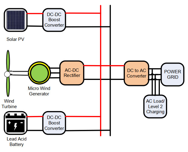
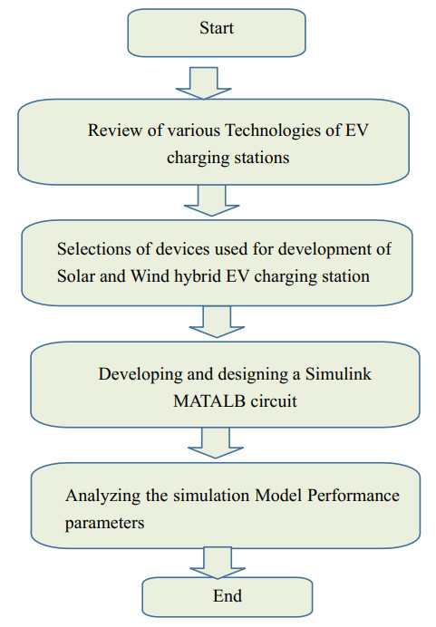
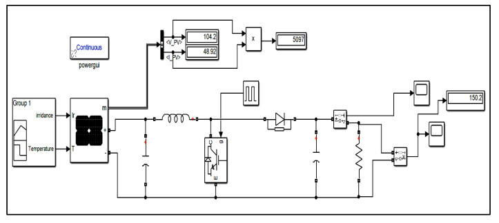
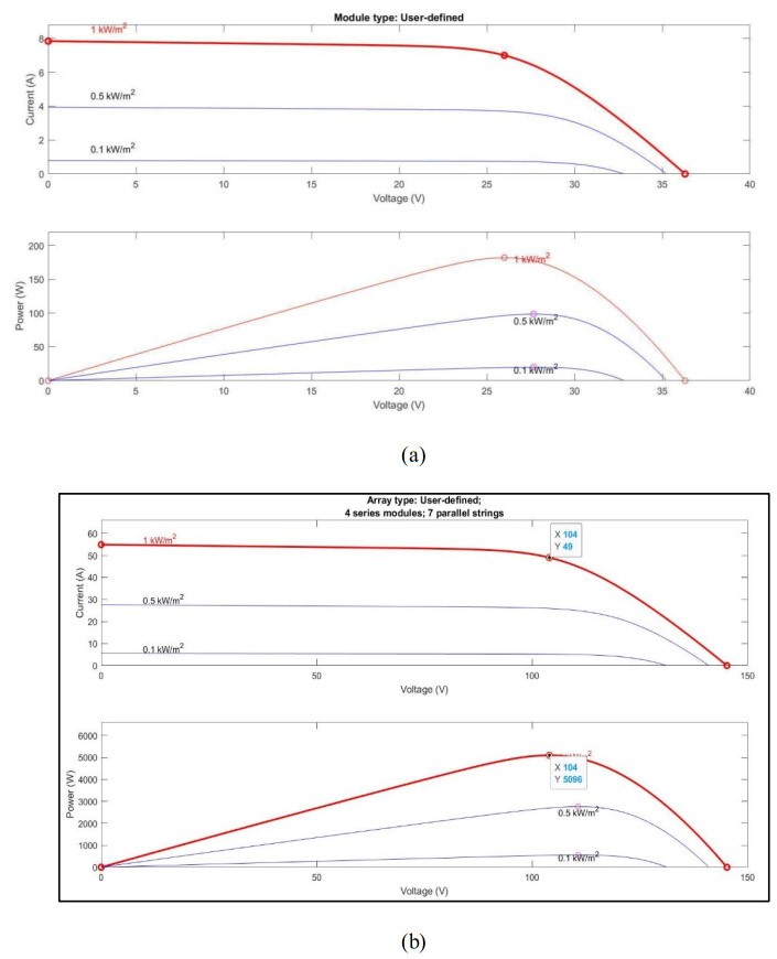
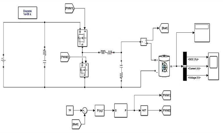
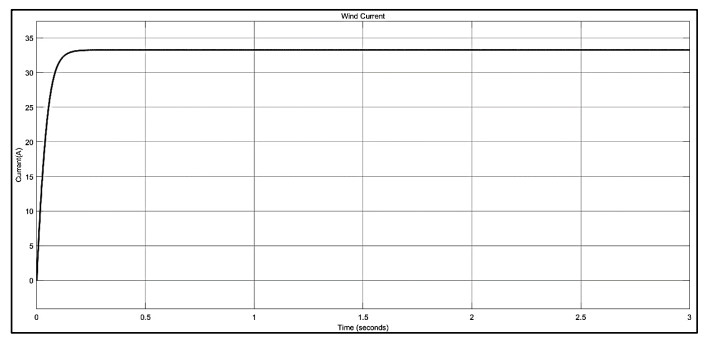
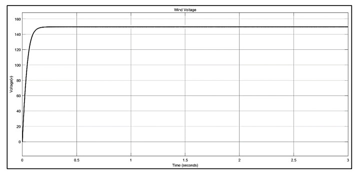
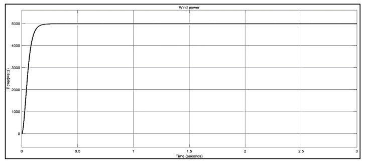
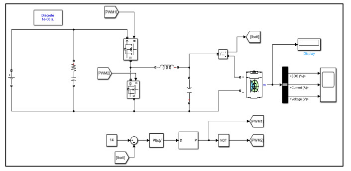
In response to escalating environmental concerns driven by greenhouse gas emissions, Pakistan, amid accelerated climate change and deteriorating air quality, struggles with power crisis. Our purpose of this research was to develop a pivotal strategy to address the power crisis and provide clean transportation facilities by involving power transitioning from fossil fuel vehicles to electric vehicles (EVs). We aimed to establish EV charging stations powered by renewable sources like solar and wind energy using grid to vehicle (V2G) mechanism. Utilizing MATLAB Simulink, an optimal electric vehicle charging system with a Level 2 fast charging mechanism was designed, aiming to significantly reduce greenhouse gas emissions from both the transportation and energy sectors. This framework aligned with global trends in climate change mitigation, providing developing countries like Pakistan with a practical solution. The results indicated a 10-kW, AC power output at 240 V coupled with an ideal 50 kWh EV battery rating, which was achieved for EV charging. The output parameters, including current voltage and power output of solar PV, micro wind, and battery levels, were used before and after the incorporation of a boost converter. Consequently, the application of a boost converter and proportional integral (PI) controller resulted in low overshoot and steady state output parameters of the proposed system. Also, the battery backup helped to optimize the power output for load driven EVs.
Citation: Mansoor Soomro, Zeeshan Ali Shaikh, Mazhar Baloch, Abdul Manan Shaikh, Sohaib Tahir Chauhdary. Development of wind and solar systems for power charging: An application of an electric vehicle to grid systems[J]. AIMS Energy, 2024, 12(3): 664-685. doi: 10.3934/energy.2024031
In response to escalating environmental concerns driven by greenhouse gas emissions, Pakistan, amid accelerated climate change and deteriorating air quality, struggles with power crisis. Our purpose of this research was to develop a pivotal strategy to address the power crisis and provide clean transportation facilities by involving power transitioning from fossil fuel vehicles to electric vehicles (EVs). We aimed to establish EV charging stations powered by renewable sources like solar and wind energy using grid to vehicle (V2G) mechanism. Utilizing MATLAB Simulink, an optimal electric vehicle charging system with a Level 2 fast charging mechanism was designed, aiming to significantly reduce greenhouse gas emissions from both the transportation and energy sectors. This framework aligned with global trends in climate change mitigation, providing developing countries like Pakistan with a practical solution. The results indicated a 10-kW, AC power output at 240 V coupled with an ideal 50 kWh EV battery rating, which was achieved for EV charging. The output parameters, including current voltage and power output of solar PV, micro wind, and battery levels, were used before and after the incorporation of a boost converter. Consequently, the application of a boost converter and proportional integral (PI) controller resulted in low overshoot and steady state output parameters of the proposed system. Also, the battery backup helped to optimize the power output for load driven EVs.

| [1] |
Connolly D, Mathiesen BV, Ridjan I (2014) A comparison between renewable transport fuels that can supplement or replace biofuels in a 100% renewable energy system. Energy 73: 110–125. https://doi.org/10.1016/j.energy.2014.05.104 doi: 10.1016/j.energy.2014.05.104

|
| [2] |
Alatai S, Salem M, Ishak D, et al. (2021) A review on state-of-the-art power converters: bidirectional, resonant, multilevel converters and their derivatives. Appl Sci 11: 10172. https://doi.org/10.3390/app112110172 doi: 10.3390/app112110172
|
| [3] |
Nasab MA, Zand M, Miri M, et al. (2024) Predicting solar power potential via an enhanced ANN through the evolution of cub to predator (ECP) optimization technique. Electr Eng, 1–12. https://doi.org/10.1007/s00202-024-02302-1 doi: 10.1007/s00202-024-02302-1
|
| [4] |
Un-Noor F, Padmanaban S, Mihet-Popa L, et al. (2017) A comprehensive study of key electric vehicle (EV) components, technologies, challenges, impacts, and future direction of development. Energies 10: 1217. https://doi.org/10.3390/en10081217 doi: 10.3390/en10081217
|
| [5] |
Dominković DF, Bačeković I, Pedersen AS, et al. (2018) The future of transportation in sustainable energy systems: Opportunities and barriers in a clean energy transition. Renewable Sustainable Energy Rev 82: 1823–1838. https://doi.org/10.1016/j.rser.2017.06.117 doi: 10.1016/j.rser.2017.06.117
|
| [6] |
Alsharif A, Tan CW, Ayop R, et al. (2021) A comprehensive review of energy management strategy in Vehicle-to-Grid technology integrated with renewable energy sources. Sustainable Energy Technol Assess 47: 101439. https://doi.org/10.1016/j.seta.2021.101439 doi: 10.1016/j.seta.2021.101439
|
| [7] |
Mastoi MS, Zhuang S, Munir HM, et al. (2022) An in-depth analysis of electric vehicle charging station infrastructure, policy implications, and future trends. Energy Rep 8: 11504–11529. https://doi.org/10.1016/j.egyr.2022.09.011 doi: 10.1016/j.egyr.2022.09.011
|
| [8] |
Das HS, Rahman MM, Li S, et al. (2020) Electric vehicles standards, charging infrastructure, and impact on grid integration: A technological review. Renewable Sustainable Energy Rev 120: 109618. https://doi.org/10.1016/j.rser.2019.109618 doi: 10.1016/j.rser.2019.109618
|
| [9] |
Caminiti CM, Merlo M, Ghazvini MAF, et al. (2024) optimHome: A shrinking horizon control architecture for bidirectional smart charging in home energy management systems. Energies 17: 1963. https://doi.org/10.3390/en17081963 doi: 10.3390/en17081963
|
| [10] |
Zhu H, Goh HH, Zhang D, et al. (2022) Key technologies for smart energy systems: Recent developments, challenges, and research opportunities in the context of carbon neutrality. J Cleaner Prod 331: 129809. https://doi.org/10.1016/j.jclepro.2021.129809 doi: 10.1016/j.jclepro.2021.129809
|
| [11] |
Barman P, Dutta L, Bordoloi S, et al., (2023) Renewable energy integration with electric vehicle technology: A review of the existing smart charging approaches. Renewable Sustainable Energy Rev 183: 113518. https://doi.org/10.1016/j.rser.2023.113518 doi: 10.1016/j.rser.2023.113518
|
| [12] |
Rehman AU, Wadud Z, Elavarasan RM, et al. (2021) An optimal power usage scheduling in smart grid integrated with renewable energy sources for energy management. IEEE Access 9: 84619–84638. https://doi.org/10.1109/ACCESS.2021.3087321 doi: 10.1109/ACCESS.2021.3087321
|
| [13] |
Wang W, Liu L, Liu J, et al. (2020) Energy management and optimization of vehicle-to-grid systems for wind power integration. CSEE J Power Energy Syst 7: 172–180. https://doi.org/10.17775/CSEEJPES.2020.01610 doi: 10.17775/CSEEJPES.2020.01610
|
| [14] |
Rietmann N, Hügler B, Lieven T (2020) Forecasting the trajectory of electric vehicle sales and the consequences for worldwide CO2 emissions. J Cleaner Prod 261: 121038. https://doi.org/10.1016/j.jclepro.2020.121038 doi: 10.1016/j.jclepro.2020.121038
|
| [15] |
Gryparis E, Papadopoulos P, Leligou HC, et al. (2020) Electricity demand and carbon emission in power generation under high penetration of electric vehicles. A European Union perspective. Energy Rep 6: 475–486. https://doi.org/10.1016/j.egyr.2020.09.025 doi: 10.1016/j.egyr.2020.09.025
|
| [16] |
Wang P, Wang D, Zhu C, et al. (2020) Stochastic management of hybrid AC/DC microgrids considering electric vehicles charging demands. Energy Rep 6: 1338–1352. https://doi.org/10.1016/j.egyr.2020.05.019 doi: 10.1016/j.egyr.2020.05.019
|
| [17] |
Lan T, Jermsittiparsert K, Alrashood ST, et al. (2021) An advanced machine learning based energy management of renewable microgrids considering hybrid electric vehicles' charging demand. Energies 14: 569. https://doi.org/10.3390/en14030569 doi: 10.3390/en14030569
|
| [18] |
Zhang L, Cheng L, Alsokhiry F, et al. (2022) A novel stochastic blockchain-based energy management in smart cities using V2S and V2G. IEEE Trans Intell Transp Syst 24: 915–922. https://doi.org/10.1109/TITS.2022.3143146 doi: 10.1109/TITS.2022.3143146
|
| [19] |
Aljohani T, Mohamed MA, Mohammed O (2024) Tri-level hierarchical coordinated control of large-scale EVs charging based on multi-layer optimization framework. Electr Power Syst Res 226: 109923. https://doi.org/10.1016/j.epsr.2023.109923 doi: 10.1016/j.epsr.2023.109923
|
| [20] |
Das S, Acharjee P, Bhattacharya A (2022) Charging scheduling of electric vehicle incorporating grid-to-vehicle and vehicle-to-grid technology considering in smart grid. IEEE Trans Ind Appl 57: 1688–1702. https://doi.org/10.1109/TIA.2020.3041808 doi: 10.1109/TIA.2020.3041808
|
| [21] |
Lee JH, Chakraborty D, Hardman SJ, et al. (2020) Exploring electric vehicle charging patterns: Mixed usage of charging infrastructure. Transp Res Part D: Transp Environ 79: 102249. https://doi.org/10.1016/j.trd.2020.102249 doi: 10.1016/j.trd.2020.102249
|
| [22] |
Hassan Q, Algburi S, Sameen AZ, et al. (2023) A review of hybrid renewable energy systems: Solar and wind-powered solutions: Challenges, opportunities, and policy implications. Results Eng 20: 101621. https://doi.org/10.1016/j.rineng.2023.101621 doi: 10.1016/j.rineng.2023.101621
|
| [23] |
Atawi IE, Al-Shetwi AQ, Magableh AM, et al. (2022) Recent advances in hybrid energy storage system integrated renewable power generation: Configuration, control, applications, and future directions. Batteries 9: 29. https://doi.org/10.3390/batteries9010029 doi: 10.3390/batteries9010029
|
| [24] |
Abraham DS, Verma R, Kanagaraj L, et al. (2021) Electric vehicles charging stations' architectures, criteria, power converters, and control strategies in microgrids. Electronics 10: 1895. https://doi.org/10.3390/electronics10161895 doi: 10.3390/electronics10161895
|
| [25] |
Carlton GJ, Sultana S (2022) Electric vehicle charging station accessibility and land use clustering: A case study of the Chicago region. J Urban Mobility 2: 100019. https://doi.org/10.1016/j.urbmob.2022.100019 doi: 10.1016/j.urbmob.2022.100019
|
| [26] |
Shams SA, Ahmadi R (2021) Dynamic optimization of solar‐wind hybrid system connected to electrical battery or hydrogen as an energy storage system. Int J Energy Res 45: 10630–10654. https://doi.org/10.1002/er.6549 doi: 10.1002/er.6549
|
| [27] |
Rajasekaran R, Rani PU (2021) Bidirectional DC-DC converter for microgrid in energy management system. Int J Electron 108: 322–343. https://doi.org/10.1080/00207217.2020.1793418 doi: 10.1080/00207217.2020.1793418
|
Figures(15) / Tables(2)

Mansoor Soomro, Zeeshan Ali Shaikh, Mazhar Baloch, Abdul Manan Shaikh, Sohaib Tahir Chauhdary. Development of wind and solar systems for power charging: An application of an electric vehicle to grid systems[J]. AIMS Energy, 2024, 12(3): 664-685. doi: 10.3934/energy.2024031


 DownLoad: