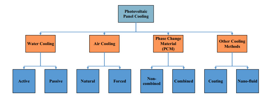
This work concerns a comparative experimental study of cooling PV panels by free and forced convection and using finned plates. To this end, four prototypes are considered: the first one with a PV panel alone without cooling techniques, the second one consists of a PV panel with a rectangular finned plate attached to its rear surface and cooled by free convection, a third prototype consists of a PV panel cooled by forced convection by three axial-flow fans and a fourth prototype consists of a PV panel with a rectangular finned plate attached to its rear surface and cooled by forced convection by three axial-flow fans. Results showed an increase of 3.01% in the efficiency of the PV panel with finned plate under forced convection, an increase of 2.55% in the efficiency of the PV panel with finned plate under free convection and an increase of 2.10% in the efficiency of the PV panel under forced convection. Economic and environmental studies are also conducted and estimations of savings per year and amount of carbon dioxide emission reductions are provided.
Citation: Tarek Ibrahim, Farouk Hachem, Mohamad Ramadan, Jalal Faraj, Georges El Achkar, Mahmoud Khaled. Cooling PV panels by free and forced convections: Experiments and comparative study[J]. AIMS Energy, 2023, 11(5): 774-794. doi: 10.3934/energy.2023038
This work concerns a comparative experimental study of cooling PV panels by free and forced convection and using finned plates. To this end, four prototypes are considered: the first one with a PV panel alone without cooling techniques, the second one consists of a PV panel with a rectangular finned plate attached to its rear surface and cooled by free convection, a third prototype consists of a PV panel cooled by forced convection by three axial-flow fans and a fourth prototype consists of a PV panel with a rectangular finned plate attached to its rear surface and cooled by forced convection by three axial-flow fans. Results showed an increase of 3.01% in the efficiency of the PV panel with finned plate under forced convection, an increase of 2.55% in the efficiency of the PV panel with finned plate under free convection and an increase of 2.10% in the efficiency of the PV panel under forced convection. Economic and environmental studies are also conducted and estimations of savings per year and amount of carbon dioxide emission reductions are provided.

| [1] |
Moqbel S (2020) Evaluating bioreactor landfill as an energy source. Int J Energy Environ Eng 12: 23–30. https://doi.org/10.1007/s40095-020-00350-4 doi: 10.1007/s40095-020-00350-4

|
| [2] |
Attar A, Albatati F (2020) Wearable thermoelectric generators as energy harvesters for wireless body sensors. Int J Energy Environ Eng 12: 131–149. https://doi.org/10.1007/s40095-020-00365-x doi: 10.1007/s40095-020-00365-x
|
| [3] |
Prasad DMR, Senthilkumar R, Lakshmanarao G, et al. (2019) A critical review on thermal energy storage materials and systems for solar applications. AIMS Energy 7: 507–526. https://doi.org/10.3934/energy.2019.4.507 doi: 10.3934/energy.2019.4.507
|
| [4] |
Alhousni FK, Ismail FB, Okonkwo PC, et al. (2022) A review of PV solar energy system operations and applications in Dhofar Oman. AIMS Energy 10: 858–884. https://doi.org/10.3934/energy.2022039 doi: 10.3934/energy.2022039
|
| [5] |
Azevedo JAR, Mendonça F (2015) Small scale wind energy harvesting with maximum power tracking. AIMS Energy 3: 297–315. https://doi.org/10.3934/energy.2015.3.297 doi: 10.3934/energy.2015.3.297
|
| [6] |
Padhee M, Karki R (2018) Bulk system reliability impacts of forced wind energy curtailment. AIMS Energy 6: 505–520. https://doi.org/10.3934/energy.2018.3.505 doi: 10.3934/energy.2018.3.505
|
| [7] |
Ali NM, Ammari H (2022) Design of a hybrid wind-solar street lighting system to power LED lights on highway poles. AIMS Energy 10: 177–190. https://doi.org/10.3934/energy.2022010 doi: 10.3934/energy.2022010
|
| [8] |
Dewi MP, Setiawan AD, Latief Y, et al. (2022) Investment decisions under uncertainties in geothermal power generation. AIMS Energy 10: 844–857. https://doi.org/10.3934/energy.2022038 doi: 10.3934/energy.2022038
|
| [9] |
Schwartzman P, Schwartzman D (2021) Can the 1.5 ℃ warming target be met in a global transition to 100% renewable energy? AIMS Energy 9: 1170–1191. https://doi.org/10.3934/energy.2021054 doi: 10.3934/energy.2021054
|
| [10] |
Ludin GA, Amin M, Aminzay A, et al. (2016) Theoretical potential and utilization of renewable energy in Afghanistan. AIMS Energy 5: 1–19. https://doi.org/10.3934/energy.2017.1.1 doi: 10.3934/energy.2017.1.1
|
| [11] |
Peura P, Sjöholm P (2015) Sustainable or distributed energy—or both? Clarifying the basic concepts of reforming the energy sector. AIMS Energy 3: 241–254. https://doi.org/10.3934/energy.2015.2.241 doi: 10.3934/energy.2015.2.241
|
| [12] |
Katutsi V, Kaddu M, Migisha AG, et al. (2021) Overview of hydropower resources and development in Uganda. AIMS Energy 9: 1299–1320. https://doi.org/10.3934/energy.2021060 doi: 10.3934/energy.2021060
|
| [13] |
Danso-Boateng E, Achaw O-W (2022) Bioenergy and biofuel production from biomass using thermochemical conversions technologies—A review. AIMS Energy 10: 585–647. https://doi.org/10.3934/energy.2022030 doi: 10.3934/energy.2022030
|
| [14] |
Da Silva MV, Ferreira V, Pinho C (2021) Determination of biomass combustion rate in a domestic fixed bed boiler. AIMS Energy 9: 1067–1096. https://doi.org/10.3934/energy.2021049 doi: 10.3934/energy.2021049
|
| [15] |
Gamil MM, Lotfy ME, Hemeida AM, et al. (2021) Optimal sizing of a residential microgrid in Egypt under deterministic and stochastic conditions with PV/WG/Biomass energy integration. AIMS Energy 9: 483–515. https://doi.org/10.3934/energy.2021024 doi: 10.3934/energy.2021024
|
| [16] |
Tien TN, Vu Q, Duy VN (2022) Novel designs of thermoelectric generator for automotive waste heat recovery: A review. AIMS Energy 10: 922–942. https://doi.org/10.3934/energy.2022042 doi: 10.3934/energy.2022042
|
| [17] |
Hage HE, Ramadan M, Jaber H, et al. (2019) A short review on the techniques of waste heat recovery from domestic applications. Energy Sources A: Recovery Util Environ 42: 3019–3034. https://doi.org/10.1080/15567036.2019.1623940 doi: 10.1080/15567036.2019.1623940
|
| [18] |
Murr R, Ramadan M, Khaled M, et al. (2019) An iterative code to investigate heat pump performance improvement by exhaust gases heat recovery. Energy Sources A: Recovery Util Environ 41: 2207–2218. https://doi.org/10.1080/15567036.2018.1555625 doi: 10.1080/15567036.2018.1555625
|
| [19] |
Khaled M, Ramadan M (2017) Study of the thermal behavior of multi tube tank in heat recovery from chimney—Analysis and optimization. Heat Transfer Eng 39: 399–409. https://doi.org/10.1080/01457632.2017.1312864 doi: 10.1080/01457632.2017.1312864
|
| [20] |
Yang F, Yu Q, Zuo Z, et al. (2019) Thermodynamic analysis of waste heat recovery of aluminum dross in electrolytic aluminum industry. Energy Sources A: Recovery Util Environ 43: 1047–1059. https://doi.org/10.1080/15567036.2019.1634163 doi: 10.1080/15567036.2019.1634163
|
| [21] |
Zafar A, Su Y, Li L, et al. (2019) The numerical simulation and wellbore modelling of steam injection and stored heat recovery from light oil reservoir. Energy Sources A: Recovery Util Environ 43: 1–16. https://doi.org/10.1080/15567036.2019.1676331 doi: 10.1080/15567036.2019.1676331
|
| [22] | Emery K, Burdick J, Caiyem Y, et al. (1996) Temperature dependence of photovoltaic cells, modules and systems. Conference Record of the Twenty Fifth IEEE Photovoltaic Specialists Conference, Washington, DC, USA, 1275–1278. http://doi.org/10.1109/PVSC.1996.564365 |
| [23] |
Yuan W, Ji J, Li Z, et al. (2018) Comparison study of the performance of two kinds of photovoltaic/thermal (PV/T) systems and a PV module at high ambient temperature. Energy 148: 1153–1161. https://doi.org/10.1016/j.energy.2018.01.121 doi: 10.1016/j.energy.2018.01.121
|
| [24] |
Mays AE, Ammar R, Hawa M, et al. (2017) Improving photovoltaic panel using finned plate of aluminum. Energy Proc 119: 812–817. https://doi.org/10.1016/j.egypro.2017.07.103 doi: 10.1016/j.egypro.2017.07.103
|
| [25] |
Hachem F, Abdulhay B, Ramadan M, et al. (2017) Improving the performance of photovoltaic cells using pure and combined phase change materials—Experiments and transient energy balance. Renewable Energy 107: 567–575. https://doi.org/10.1016/j.renene.2017.02.032 doi: 10.1016/j.renene.2017.02.032
|
| [26] |
Nižetić S, Čabo FG, Marinić-Kragić I, et al. (2016) Experimental and numerical investigation of a backside convective cooling mechanism on photovoltaic panels. Energy 111: 211–225. https://doi.org/10.1016/j.energy.2016.05.103 doi: 10.1016/j.energy.2016.05.103
|
| [27] |
Al-Waeli AHA, Chaichan MT, Kazem HA, et al. (2018) Comparison study of indoor/outdoor experiments of a photovoltaic thermal PV/T system containing SiC nanofluid as a coolant. Energy 151: 33–44. https://doi.org/10.1016/j.energy.2018.03.040 doi: 10.1016/j.energy.2018.03.040
|
| [28] |
Kaldellis JK, Zafirakis D (2012) Experimental investigation of the optimum photovoltaic panels' tilt angle during the summer period. Energy 38: 305–314. https://doi.org/10.1016/j.energy.2011.11.058 doi: 10.1016/j.energy.2011.11.058
|
| [29] |
Irshad K, Habib K, Basrawi F, et al. (2017) Study of a thermoelectric air duct system assisted by photovoltaic wall for space cooling in tropical climate. Energy 119: 504–522. https://doi.org/10.1016/j.energy.2016.10.110 doi: 10.1016/j.energy.2016.10.110
|
| [30] |
Luo Y, Zhang L, Liu Z, et al. (2018) Numerical evaluation on energy saving potential of a solar photovoltaic thermoelectric radiant wall system in cooling dominant climates. Energy 142: 384–399. https://doi.org/10.1016/j.energy.2017.10.050 doi: 10.1016/j.energy.2017.10.050
|
| [31] |
Hussien A, Eltayesh A, El-Batsh HM (2023) Experimental and numerical investigation for PV cooling by forced convection. Alex Eng J 64: 427–440. https://doi.org/10.1016/j.aej.2022.09.006 doi: 10.1016/j.aej.2022.09.006
|
| [32] |
Wang Y, Zhao T, Cao Z, et al. (2023) Numerical study on the forced convection enhancement of flat-roof integrated photovoltaic by passive components. Energy Build 289: 113063. https://doi.org/10.1016/j.enbuild.2023.113063 doi: 10.1016/j.enbuild.2023.113063
|
| [33] |
Ahmad EZ, Fazlizan A, Jarimi H, et al. (2021) Enhanced heat dissipation of truncated multi-level fin heat sink (MLFHS) in case of natural convection for photovoltaic cooling. Case Stud Therm Eng 28: 101578. https://doi.org/10.1016/j.csite.2021.101578 doi: 10.1016/j.csite.2021.101578
|
| [34] |
Yildirim MA, Cebula A, Sułowicz M (2022) A cooling design for photovoltaic panels—Water-based PV/T system. Energy 256: 124654. https://doi.org/10.1016/j.energy.2022.124654 doi: 10.1016/j.energy.2022.124654
|
| [35] |
Bevilacqua P, Bruno R, Rollo A, et al. (2022) A novel thermal model for PV panels with back surface spray cooling. Energy 255: 124401. https://doi.org/10.1016/j.energy.2022.124401 doi: 10.1016/j.energy.2022.124401
|
| [36] |
Salman AHA, Hilal KH, Ghadhban SA (2022) Enhancing performance of PV module using water flow through porous media. Case Stud Therm Eng 34: 102000. https://doi.org/10.1016/j.csite.2022.102000 doi: 10.1016/j.csite.2022.102000
|
| [37] |
Vaillon R, Dupré O, Cal RB, et al. (2018) Pathways for mitigating thermal losses in solar photovoltaics. Sci Rep 8: 13163. https://doi.org/10.1038/s41598-018-31257-0 doi: 10.1038/s41598-018-31257-0
|
| [38] |
Glick A, Ali N, Bossuyt J, et al. (2020) Utility-scale solar PV performance enhancements through system-level modifications. Sci Rep 10: 10505. https://doi.org/10.1038/s41598-020-66347-5 doi: 10.1038/s41598-020-66347-5
|
| [39] |
Stanislawski BJ, Margairaz F, Cal RB, et al. (2020) Potential of module arrangements to enhance convective cooling in solar photovoltaic arrays. Renewable Energy 157: 851–858. https://doi.org/10.1016/j.renene.2020.04.049 doi: 10.1016/j.renene.2020.04.049
|
| [40] |
Glick A, Smith SE, Ali N, et al. (2020) Influence of flow direction and turbulence intensity on heat transfer of utility-scale photovoltaic solar farms. Sol Energy 207: 173–182. https://doi.org/10.1016/j.solener.2020.05.061 doi: 10.1016/j.solener.2020.05.061
|
| [41] |
Prilliman M, Smith SE, Stanislawski BJ, et al (2022) Technoeconomic analysis of changing PV array convective cooling through changing array spacing. IEEE J Photovoltaic 12: 1586–1592. https://doi.org/10.1109/jphotov.2022.3201464 doi: 10.1109/jphotov.2022.3201464
|
| [42] |
Stanislawski B, Harman T, Silverman TJ, et al. (2022) Row spacing as a controller of solar module temperature and power output in solar farms. J Renewable Sustainable Energy 14: 063702. https://doi.org/10.1063/5.0123641 doi: 10.1063/5.0123641
|
| [43] |
Smith SE, Stanislawski BJ, Eng BK, et al. (2022) Viewing convection as a solar farm phenomenon broadens modern power predictions for solar photovoltaics. J Renewable Sustainable Energy 14: 063502. https://doi.org/10.1063/5.0105649 doi: 10.1063/5.0105649
|
| [44] |
Glick A, Ali N, Bossuyt J, et al. (2020) Infinite photovoltaic solar arrays: Considering flux of momentum and heat transfer. Renewable Energy 156: 791–803. https://doi.org/10.1016/j.renene.2020.03.183 doi: 10.1016/j.renene.2020.03.183
|


Figures(16) / Tables(3)

Tarek Ibrahim, Farouk Hachem, Mohamad Ramadan, Jalal Faraj, Georges El Achkar, Mahmoud Khaled. Cooling PV panels by free and forced convections: Experiments and comparative study[J]. AIMS Energy, 2023, 11(5): 774-794. doi: 10.3934/energy.2023038


 DownLoad: