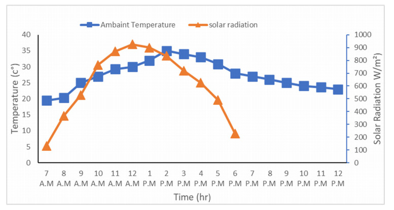
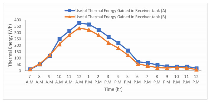
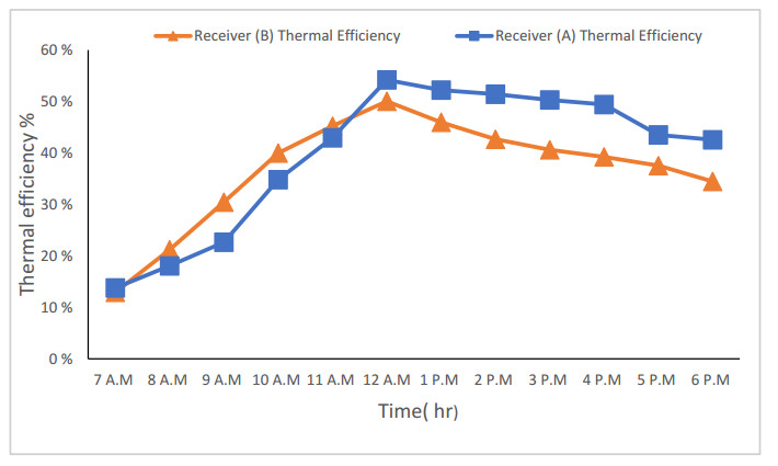
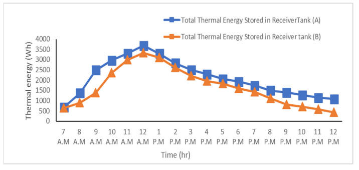
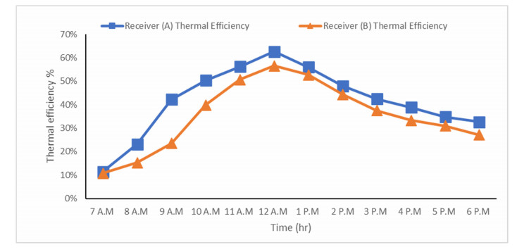
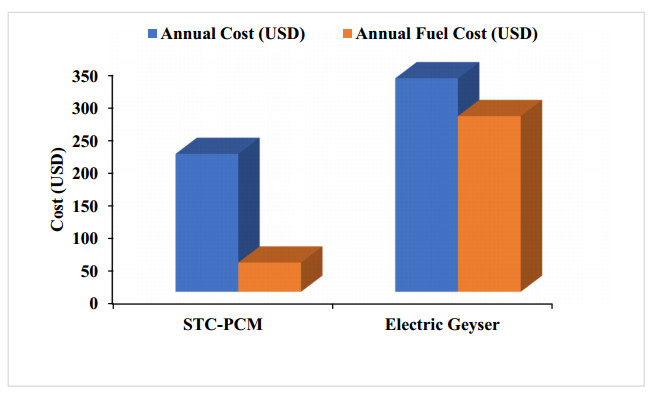
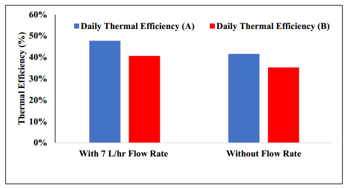
The use of phase change materials in solar thermal collectors improves their thermal performance significantly. In this paper, a comparative study is conducted systematically between two solar receivers. The first receiver contains paraffin wax, while the other does not. The goal was to find out to which degree paraffin wax can enhance the energy storage and thermal efficiency of evacuated tubes solar collectors. Measurements of water temperature and solar radiation were recorded on a few days during August of 2021. The experimental analysis depended on two stages. The first stage had a flow rate of 7 L/hr, and the second stage had no flow rate. A flow rate of 7 L/hr gave an efficiency of 47.7% of the first receiver with phase-change material, while the second conventional receiver had an efficiency rate of 40.6%. The thermal efficiency of the first receiver during the day at which no flow rate was applied was 41.6%, while the second one had an efficiency rate of 35.2%. The study's significant results indicated that using paraffin wax in solar evacuated tube water-in-glass thermal collectors can enhance their thermal energy storage by about 8.6% and efficiency by about 7%. Moreover, the results revealed that the solar thermal collector containing paraffin wax had an annual cost of 211 USD/year. At the same time, the receiver's yearly fuel cost was 45 USD. Compared to an electrical geyser, the annual cost reached 327 USD, with an annual fuel cost equaled 269 USD. The first receiver's payback period was 5.35 years.
Citation: Akthem Mohi Al-Abdali, Handri Ammari. Thermal energy storage using phase-change material in evacuated-tubes solar collector[J]. AIMS Energy, 2022, 10(3): 486-505. doi: 10.3934/energy.2022024
The use of phase change materials in solar thermal collectors improves their thermal performance significantly. In this paper, a comparative study is conducted systematically between two solar receivers. The first receiver contains paraffin wax, while the other does not. The goal was to find out to which degree paraffin wax can enhance the energy storage and thermal efficiency of evacuated tubes solar collectors. Measurements of water temperature and solar radiation were recorded on a few days during August of 2021. The experimental analysis depended on two stages. The first stage had a flow rate of 7 L/hr, and the second stage had no flow rate. A flow rate of 7 L/hr gave an efficiency of 47.7% of the first receiver with phase-change material, while the second conventional receiver had an efficiency rate of 40.6%. The thermal efficiency of the first receiver during the day at which no flow rate was applied was 41.6%, while the second one had an efficiency rate of 35.2%. The study's significant results indicated that using paraffin wax in solar evacuated tube water-in-glass thermal collectors can enhance their thermal energy storage by about 8.6% and efficiency by about 7%. Moreover, the results revealed that the solar thermal collector containing paraffin wax had an annual cost of 211 USD/year. At the same time, the receiver's yearly fuel cost was 45 USD. Compared to an electrical geyser, the annual cost reached 327 USD, with an annual fuel cost equaled 269 USD. The first receiver's payback period was 5.35 years.

| [1] |
Ghosh SK (2020) Fossil fuel consumption trend and global warming scenario: Energy overview. Glob J Eng Sci, 5. https://doi.org/10.33552/gjes.2020.05.000606 doi: 10.33552/gjes.2020.05.000606

|
| [2] |
Saini V, Tripathi R, Tiwari GN, et al. (2018) Electrical and thermal energy assessment of series connected N partially covered photovoltaic thermal (PVT)-compound parabolic concentrator (CPC) collector for different solar cell materials. Appl Therm Eng 128: 1611-1623. https://doi.org/10.1016/j.applthermaleng.2017.09.119 doi: 10.1016/j.applthermaleng.2017.09.119
|
| [3] |
Shamshirgaran SR, Al-Kayiem HH, Sharma K, et al. (2020) State of the art of techno-economics of nanofluid-laden flat-plate solar collectors for sustainable accomplishment. Sustainability, 12. https://doi.org/10.3390/su12219119 doi: 10.3390/su12219119
|
| [4] |
Abd-Elhady MS, Nasreldin M, Elsheikh MN (2018) Improving the performance of evacuated tube heat pipe collectors using oil and foamed metals. Ain Shams Eng J 9: 2683-2689. https://doi.org/10.1016/j.asej.2017.10.001 doi: 10.1016/j.asej.2017.10.001
|
| [5] |
Venkatacha C, Mariam SG, Chimdo Anc A (2018) Thermal and economic analysis review on flat plate, parabolic trough and evacuated tube solar collectors for process heat applications. J Appl Sci 19: 1-8. https://doi.org/10.3923/jas.2019.1.8 doi: 10.3923/jas.2019.1.8
|
| [6] | Benchara EH, Jennah S, Belouggadia N, et al. (2020) Thermal energy storage by phase change materials suitable for solar water heaters: An updated review. In: 2020 IEEE 2nd International Conference on Electronics, Control, Optimization and Computer Science, ICECOCS 2020: 1-10. https://doi.org/10.1109/ICECOCS50124.2020.9314561 |
| [7] |
Reddy RM, Nallusamy N, Hariprasad T (2012) Solar energy based thermal energy storage system using phase change materials. Int J Renewable Energy Technol 3: 11-23. https://doi.org/10.1504/ijret.2012.043905 doi: 10.1504/ijret.2012.043905
|
| [8] | Lin W, Ma Z, Ren H (2020) Solar thermal energy storage using paraffins as phase change materials for air conditioning in the built environment. In: Paraffin-an Overview. https://doi.org/10.5772/intechopen.86025 |
| [9] |
Sadeghi G, Pisello AL, Nazari S (2021) Empirical data-driven multi-layer perceptron and radial basis function techniques in predicting the performance of nanofluid-based modified tubular solar collectors. J Clean Prod 295: 126409. https://doi.org/10.1016/j.jclepro.2021.126409 doi: 10.1016/j.jclepro.2021.126409
|
| [10] |
Yeh CY, Boonk KJF, Sadeghi G, et al. (2022) Experimental and numerical analysis of thermal performance of shape stabilized PCM in a solar thermal collector. Case Stud Therm Eng 30: 101706. https://doi.org/10.1016/j.csite.2021.101706 doi: 10.1016/j.csite.2021.101706
|
| [11] |
Shoeibi S, Kargarsharifabad H, Mirjalily SAA, et al. (2022) A comprehensive review of nano-enhanced phase change materials on solar energy applications. J Energy Storage 50: 104262. https://doi.org/10.1016/j.est.2022.104262 doi: 10.1016/j.est.2022.104262
|
| [12] | Hussein HA, Abed AH, Abdulmunem AR (2016) An experimental investigation of using aluminum foam matrix integrated with paraffin wax as a thermal storage material in a solar heater. Proceeding of the 2nd Sustainable & Renewable Energy Conference, Baghdad-Iraq, 26-27. Available from: https://www.academia.edu/35718536/An_experimental_investigation_of_using_aluminum_foam_matrix_integrated_with_paraffin_wax_as_a_thermal_storage_material_in_a_solar_heater. |
| [13] |
Regin AF, Solanki SC, Saini JS (2006) Latent heat thermal energy storage using cylindrical capsule: Numerical and experimental investigations. Renewable Energy 31: 2025-2041. https://doi.org/10.1016/j.renene.2005.10.011 doi: 10.1016/j.renene.2005.10.011
|
| [14] |
Manoj Kumar P, Mylsamy K (2019) Experimental investigation of solar water heater integrated with a nanocomposite phase change material: Energetic and exergetic approach. J Therm Anal Calorim 136: 121-132. https://doi.org/10.1007/s10973-018-7937-9 doi: 10.1007/s10973-018-7937-9
|
| [15] |
Chopra K, Tyagi V, Pathak AK (2019) Experimental performance evaluation of a novel designed phase change material integrated manifold heat pipe evacuated tube solar collector system. Energy Convers Manag 198: 111896. https://doi.org/10.1016/j.enconman.2019.111896 doi: 10.1016/j.enconman.2019.111896
|
| [16] |
Carnevale E, Lombardi L, Zanchi L (2014) Life cycle assessment of solar energy systems: Comparison of photovoltaic and water thermal heater at domestic scale. Energy 77: 434-446. https://doi.org/10.1016/j.energy.2014.09.028 doi: 10.1016/j.energy.2014.09.028
|
| [17] |
Ameen M, Xiaochan W, Yaseen M, et al. (2018) Performance evaluation of root zone heating system developed with sustainable materials for application in low temperatures. Sustainability 10: 4130. https://doi.org/10.3390/su10114130 doi: 10.3390/su10114130
|
| [18] |
Algarni S, Mellouli S, Alqahtani T (2020) Experimental investigation of an evacuated tube solar collector incorporating nano-enhanced PCM as a thermal booster. Appl Therm Eng 180: 115831. https://doi.org/10.1016/j.applthermaleng.2020.115831 doi: 10.1016/j.applthermaleng.2020.115831
|
| [19] |
Betancourt ROJ, López JMG, Espejo EB, et al. (2020) Iot-based electricity bill for domestic applications. Sensors 20: 6178. https://doi.org/10.3390/s20216178 doi: 10.3390/s20216178
|
| [20] | Tangwe S, Simon M, Meyer E (2015) Quantifying residential hot water production savings by retrofitting geysers with air source heat pumps. In: Proceedings of the 23rd Conference on the Domestic Use of Energy, DUE 2015, 235-241. https://doi.org/10.1109/DUE.2015.7102986 |
| [21] |
Evangelisti L, de Lieto Vollaro R, Asdrubali F (2019) Latest advances on solar thermal collectors: A comprehensive review. Renewable Sustainable Energy Rev 114: 109318. https://doi.org/10.1016/j.rser.2019.109318 doi: 10.1016/j.rser.2019.109318
|
Figures(11) / Tables(4)

Akthem Mohi Al-Abdali, Handri Ammari. Thermal energy storage using phase-change material in evacuated-tubes solar collector[J]. AIMS Energy, 2022, 10(3): 486-505. doi: 10.3934/energy.2022024


 DownLoad: