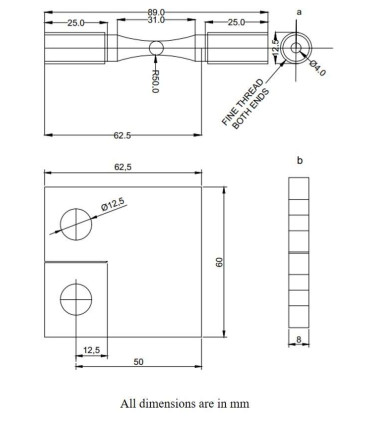
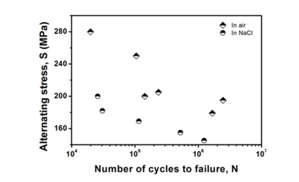
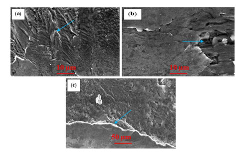
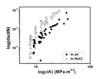
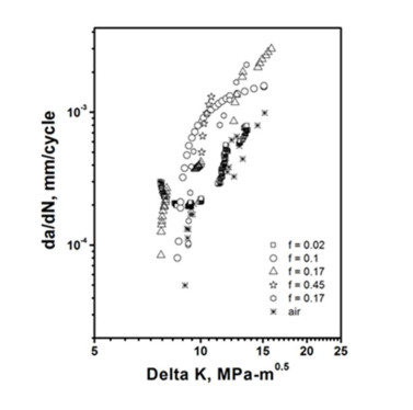
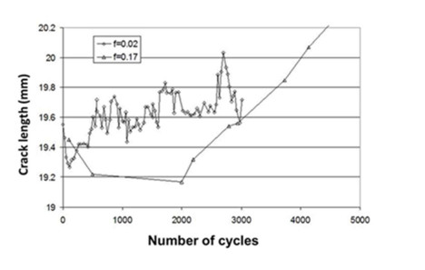
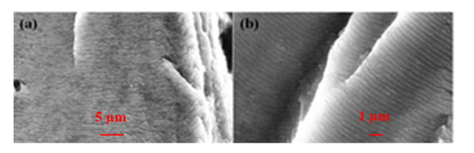
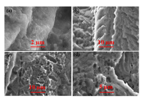
Aluminium is considered a green metal due to its environmental responsive characteristics. The 7475-T7351 aluminum alloy is extensively used in automotive and aerospace applications due to its light weight and high strength. In the present work, the effects of the corrosive environment on the high cycle fatigue (HCF) behaviors of the 7475-T7351 aluminum alloy was investigated. The aqueous solution of sodium chloride was used for solution treatment. The HCF test was performed on pre-cracked specimens using a servo-hydraulic universal testing machine, Instron 8800. The fractured specimens were characterized using a scanning electron microscope. It was observed that the crack propagation occurred through anodic dissolution at high stress and a significant crack tip blunting and crack extension occurred. However, no appreciable change in crack growth was noticed over the lower frequency range of 0.1 to 0.9 Hz. The slower growth rate envisages oxide debris formation between the cracked faces. When the alloy was treated under corrosive environments, the HCF tests depicted that the fatigue life reduces up to two orders of magnitude. The corrosion pits induced the crack initiation in stage-I at lower alternating stress; however, the fatigue crack growth rate (FCGR) was increased in the corrosive environment. The transition from stage-I to stage-II occurred at a lower stress intensity range (∆K) level; it was due to the combined effects of corrosion, hydrogen embrittlement, active path dissolution, and stress concentration. The corrosion fatigue test at low frequency also depicted a slower FCGR as compared to its moderate frequency counterpart and showed an irregular crack growth behavior.
Citation: Pawan Kumar, B B Verma. Propagation of corrosion induced fatigue crack in aluminum alloy[J]. AIMS Materials Science, 2022, 9(3): 512-521. doi: 10.3934/matersci.2022030
Aluminium is considered a green metal due to its environmental responsive characteristics. The 7475-T7351 aluminum alloy is extensively used in automotive and aerospace applications due to its light weight and high strength. In the present work, the effects of the corrosive environment on the high cycle fatigue (HCF) behaviors of the 7475-T7351 aluminum alloy was investigated. The aqueous solution of sodium chloride was used for solution treatment. The HCF test was performed on pre-cracked specimens using a servo-hydraulic universal testing machine, Instron 8800. The fractured specimens were characterized using a scanning electron microscope. It was observed that the crack propagation occurred through anodic dissolution at high stress and a significant crack tip blunting and crack extension occurred. However, no appreciable change in crack growth was noticed over the lower frequency range of 0.1 to 0.9 Hz. The slower growth rate envisages oxide debris formation between the cracked faces. When the alloy was treated under corrosive environments, the HCF tests depicted that the fatigue life reduces up to two orders of magnitude. The corrosion pits induced the crack initiation in stage-I at lower alternating stress; however, the fatigue crack growth rate (FCGR) was increased in the corrosive environment. The transition from stage-I to stage-II occurred at a lower stress intensity range (∆K) level; it was due to the combined effects of corrosion, hydrogen embrittlement, active path dissolution, and stress concentration. The corrosion fatigue test at low frequency also depicted a slower FCGR as compared to its moderate frequency counterpart and showed an irregular crack growth behavior.

| [1] |
Bayoumi MR (1993) Fatigue behaviour of a commercial aluminium alloy in sea water at different temperatures. Eng Fract Mech 45: 297-307. https://doi.org/10.1016/0013-7944(93)90015-K doi: 10.1016/0013-7944(93)90015-K

|
| [2] |
Bertolini R, Simonetto E, Pezzato L, et al. (2021) Mechanical and corrosion resistance properties of AA7075-T6 sub-zero formed sheets. Int J Adv Manuf Technol 115: 2801-2824. https://doi.org/10.1007/s00170-021-07333-7 doi: 10.1007/s00170-021-07333-7
|
| [3] |
Hoeppner DW, Arriscorreta CA (2012) Exfoliation corrosion and pitting corrosion and their role in fatigue predictive modeling: State-of-the-art review. Int J Aerosp Eng 2012: 1-29. https://doi.org/10.1155/2012/191879 doi: 10.1155/2012/191879
|
| [4] |
Sharma MM, Tomedi JD, Parks JM (2015) A microscopic study on the corrosion fatigue of ultra-fine grained and conventional Al-Mg alloy. Corros Sci 93: 180-190. https://doi.org/10.1016/j.corsci.2015.01.020 doi: 10.1016/j.corsci.2015.01.020
|
| [5] |
El May M, Palin-Luc T, Saintier N, et al. (2013) Effect of corrosion on the high cycle fatigue strength of martensitic stainless steel X12CrNiMoV12-3. Int J Fatigue 47: 330-339. https://doi.org/10.1016/j.ijfatigue.2012.09.018 doi: 10.1016/j.ijfatigue.2012.09.018
|
| [6] |
Wang QY, Kawagoishi N, Chen Q (2003) Effect of pitting corrosion on very high cycle fatigue behavior. Scr Mater 49: 711-716. https://doi.org/10.1016/S1359-6462(03)00365-8 doi: 10.1016/S1359-6462(03)00365-8
|
| [7] |
Ricker RE, Duquette DJ (1988) The role of hydrogen in corrosion fatigue of high purity Al-Zn-Mg exposed to water vapor. Metall Trans A 19: 1775-1783. https://doi.org/10.1007/BF02645146 doi: 10.1007/BF02645146
|
| [8] |
Pérez-Mora R, Palin-Luc T, Bathias C, et al. (2015) Very high cycle fatigue of a high strength steel under sea water corrosion: A strong corrosion and mechanical damage coupling. Int J Fatigue 74: 156-165. https://doi.org/10.1016/j.ijfatigue.2015.01.004 doi: 10.1016/j.ijfatigue.2015.01.004
|
| [9] |
Bradshaw FJ, Wheeler C (1969) The influence of gaseous environment and fatigue frequency on the growth of fatigue cracks in some aluminum alloys. Int J Fract Mech 5: 255-268. https://doi.org/10.1007/BF00190956 doi: 10.1007/BF00190956
|
| [10] |
DuQuesnay DL, Underhill PR, Britt HJ (2003) Fatigue crack growth from corrosion damage in 7075-T6511 aluminium alloy under aircraft loading. Int J Fatigue 25: 371-377. https://doi.org/10.1016/S0142-1123(02)00168-8 doi: 10.1016/S0142-1123(02)00168-8
|
| [11] |
Hamano R (1996) On the transition of fatigue crack growth from stage i to stage II in a corrosive environment. Metall Mater Trans A 27,471-476. https://doi.org/10.1007/BF02648426 doi: 10.1007/BF02648426
|
| [12] |
Verma BB, Atkinson JD, Kumar M (2001) Study of fatigue behaviour of 7475 aluminium alloy. Bull Mater Sci 24: 231-236. https://doi.org/10.1007/BF02710107 doi: 10.1007/BF02710107
|
| [13] |
Verma BB, Mallik M, Atkinson JD, et al. (2012) Fatigue crack initiation and growth behavior of 7475 Aluminium alloy in air and aggressive environment. Adv Mater Res 428: 133-136. https://doi.org/10.4028/www.scientific.net/AMR.428.133 doi: 10.4028/www.scientific.net/AMR.428.133
|
| [14] |
Gingell ADB, King JE (1997) The effect of frequency and microstructure on corrosion fatigue crack propagation in high strength aluminium alloys. Acta Mater 45, 3855-3870. https://doi.org/10.1016/S1359-6454(97)00033-5 doi: 10.1016/S1359-6454(97)00033-5
|
| [15] | Jahn MT, Luo J (1988) Tensile and fatigue properties of a thermomechanically treated 7475 aluminium alloy. J Mater Sci 23: 4115-4120. |
| [16] |
Wang R (2008) A fracture model of corrosion fatigue crack propagation of aluminum alloys based on the material elements fracture ahead of a crack tip. Int J Fatigue 30: 1376-1386. https://doi.org/10.1016/j.ijfatigue.2007.10.007 doi: 10.1016/j.ijfatigue.2007.10.007
|
| [17] | Dieter GE, Bacon D (1976) Mechanical Metallurgy, New York: McGraw-Hill. |
Figures(8)

Pawan Kumar, B B Verma. Propagation of corrosion induced fatigue crack in aluminum alloy[J]. AIMS Materials Science, 2022, 9(3): 512-521. doi: 10.3934/matersci.2022030


 DownLoad: